High-precision reference voltage integration sampling circuit

A reference voltage and sampling circuit technology, applied in the direction of adjusting electrical variables, control/regulation systems, instruments, etc., can solve problems such as low precision, increased chip development cycle and complexity, differential line adjustment rate and load adjustment rate, etc., to achieve Simple circuit structure, high precision of constant current output, excellent effect of line regulation and load regulation

Active Publication Date: 2015-07-15
SHANGHAI BRIGHT POWER SEMICONDUCTOR CO LTD
View PDF6 Cites 0 Cited by
  • Summary
  • Abstract
  • Description
  • Claims
  • Application Information

AI Technical Summary

Problems solved by technology

These different algorithms and circuits greatly increase the cycle and complexity of chip development. At the same time, some open-loop constant current algorithms also bring problems such as low precision, differential line adjustment rate and load regulation rate.

Method used


Image

  • High-precision reference voltage integration sampling circuit

Examples


Embodiment

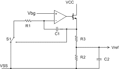
[0019] Such as figure 1 The high-precision reference voltage integral sampling circuit shown includes a single-pole double-throw switch S1, a third resistor R3, a second resistor R2, an amplifier and a field effect tube, and the output terminal of the amplifier is connected to the gate of the field effect tube , the inverting input terminal of the amplifier is connected to the source of the field effect transistor through the first capacitor C1; the second capacitor C2 is connected in parallel to the second resistor R2, and one end is connected to the field effect transistor through the third resistor R3 The source of the SPDT switch S1 is grounded, and the two fixed ends of the SPDT switch S1 are respectively connected to the ground and the source of the field effect transistor. The moving end of the SPDT switch S1 passes through the first resistor R1 Connect to the inverting input of the amplifier.

[0020] In order to facilitate the control of the resistance ratio, the thi...


PUM


Abstract

The invention discloses a high-precision reference voltage integration sampling circuit which comprises a single-pole double-throw switch S1, a resistor R3, a resistor R2, an amplifier and a field-effect tube. The output end of the amplifier is connected to the grid of the field-effect tube. The inverted input end of the amplifier is connected to the source of the field-effect tube through a capacitor C1. The resistor R2 is parallelly connected with a capacitor C2. One end of the resistor R2 is connected to the source of the field-effect tube through the resistor R3, and the other end thereof is grounded. Two fixed ends of the single-pole double-throw switch S1 are respectively connected with the source of the field-effect tube. The movable end of the single-pole double-throw switch S1 is connected to the inverted input end of the amplifier through a resistor R1. The high-precision reference voltage integration sampling circuit has the advantages that the circuit is simple in structure, high in constant current output precision by utilizing the closed-loop control constant current principle, and excellent in linear and load adjustment.

Description

technical field [0001] The invention relates to the field of integrated circuits, in particular to a high-precision reference voltage integral sampling circuit. Background technique [0002] In recent years, due to the gradual improvement of the global awareness of green environmental protection, LED lighting products have been vigorously developed and gradually entered thousands of households. In LED lighting products, the AC-DC LED drive power supply circuit provides power for the LED, and because the LED (Light Emitting Diode) is a current device, the luminous brightness is greatly affected by the current, so the LED drive power supply needs to provide stable power for the LED. Constant current output. Currently, critical current conduction mode (BCM) and disconnection control mode (DCM) are widely used in LED lighting power drivers to achieve constant current output control. In order to achieve higher power efficiency, some power driver chips use a quasi-resonant contr...

Claims


Application Information

Patent Timeline
Patent Type & Authority Patents(China)
IPC IPC(8): G05F1/56
Inventor 陈雪松易坤高继赵方麟
Owner SHANGHAI BRIGHT POWER SEMICONDUCTOR CO LTD
Why Eureka
Try Eureka