
Compensation device and compensation method of current filtering and dead zone of permanent magnet synchronous motor

A technology of permanent magnet synchronous motor and dead zone compensation, which is applied in the control of electromechanical transmission, control of generator, motor generator control, etc.

Active Publication Date: 2014-03-26
TSINGHUA UNIV
View PDF3 Cites 48 Cited by
  • Summary
  • Abstract
  • Description
  • Claims
  • Application Information

AI Technical Summary

Problems solved by technology

For the one-beat lag problem of dead zone compensation, there are few studies at present

Method used


Image

  • Compensation device and compensation method of current filtering and dead zone of permanent magnet synchronous motor
  • Compensation device and compensation method of current filtering and dead zone of permanent magnet synchronous motor
  • Compensation device and compensation method of current filtering and dead zone of permanent magnet synchronous motor

Examples


Embodiment Construction

[0058] The present invention will be described in detail below in conjunction with the accompanying drawings and embodiments.

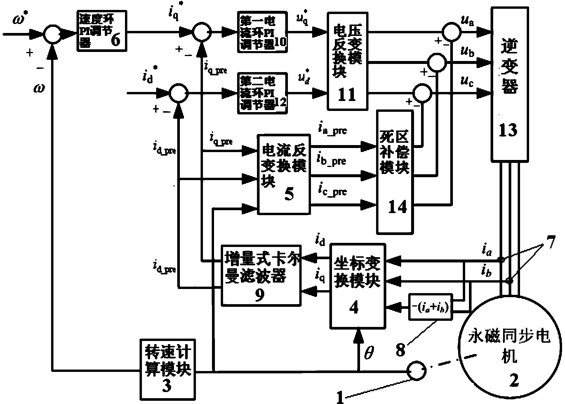
[0059] Such as figure 1 As shown, taking the permanent magnet synchronous motor servo system as an example, the present invention includes a position sensor 1, a permanent magnet synchronous motor (PMSM) 2, a speed calculation module 3, a coordinate transformation module 4, a current inverse transformation module 5, and a speed loop PI regulator 6. Current sensor 7, summation module 8, incremental Kalman filter 9, first current loop PI regulator 10, voltage inverse conversion module 11, second current loop PI regulator 12, inverter 13 and die Zone Compensation Module 14 . Wherein the coordinate transformation module 4, the incremental Kalman filter 9 and the first current loop PI regulator 10 constitute the q-axis current loop; the coordinate transformation module 4, the incremental Kalman filter 9 and the second current loop PI regulator 12 forms t...


PUM


Abstract

The invention relates to a compensation device and a compensation method of current filtering and the dead zone of a permanent magnet synchronous motor. The input end of a position sensor is connected with the output end of the permanent magnet synchronous motor, and the output end of the position sensor is connected with a rotating speed calculation module, a coordinate transformation module and a current inverse transformation module respectively. The output value of the rotating speed calculation module is used as the input of a speed ring PI adjuster. A current sensor inputs the detected two-phase current of the permanent magnet synchronous motor to the coordinate transformation module through a summation module, meanwhile the two-phase current is input into the coordinate transformation module, the coordinate transformation module transforms the coordinate of three-phase currents and then inputs the currents to an incremental kalman filter, and the output end of the incremental kalman filter is connected with the current inverse transformation module, a q-axis current ring and a d-axis current ring. The output end of a first current ring PI adjuster and the output end of a second current ring PI adjuster are connected with an inverter through a voltage inverse transformation module, the output end of the current inverse transformation module is connected with the input end of a dead zone compensation module, the output end of the dead zone compensation module is connected with the input end of the inverter, and the output end of the inverter is connected with the input end of the permanent magnet synchronous motor.

Description

technical field [0001] The invention relates to a motor current filtering and dead zone compensation device and compensation method, in particular to a permanent magnet synchronous motor current filtering and dead zone compensation device and compensation method. Background technique [0002] Permanent magnet synchronous motors have the advantages of high efficiency, high power density, and no carbon brushes, and have been widely used in servo applications. The actual system generally contains a certain degree of noise. The current noise sources of the permanent magnet synchronous motor servo system can be divided into two types. One is the white noise caused by non-ideal factors such as interference and sampling error, which is unavoidable. The other is that because the system is in a state of closed-loop control, the original white noise is adjusted as an input error, causing frequent disturbances in the system output, thereby causing greater noise. For this type of noise...

Claims


Application Information

Patent Timeline
Patent Type & Authority Applications(China)
IPC IPC(8): H02P21/05H02P6/10
Inventor 肖曦王伟华孙凯丁有爽
Owner TSINGHUA UNIV
Learn More