
Gas-liquid guiding column plate

A tray and gas-liquid technology, which is applied in the field of vapor-liquid mass transfer equipment in the chemical separation process, can solve problems such as inappropriate downcomer liquid seal height, uneven liquid velocity distribution, and affecting the normal flow of liquid phase, etc., to achieve vapor-liquid mass transfer. Increased liquid mass transfer area, uniform gas-liquid phase distribution, and increased gas-liquid mass transfer area

Active Publication Date: 2014-04-02
河北化大科技有限公司
View PDF5 Cites 1 Cited by
  • Summary
  • Abstract
  • Description
  • Claims
  • Application Information

AI Technical Summary

Problems solved by technology

At the same time, further studies have found that in the rectangular main flow area between the two weirs, the liquid velocity distribution is not uniform, and the liquid flow in the arcuate area is divided into a slow flow area and a regurgitation area. This uneven flow of liquid seriously affects the Plate efficiency
[0005] It is the characteristic of the downcomer to provide a medium for the transfer of the liquid phase between the trays. If the liquid phase load is too large, it will easily cause the liquid phase in the downcomer to block, prevent the normal flow of the liquid, and cause the tray to flood, that is, the tower is flooded. If the phase load is too low, the liquid seal height of the downcomer will be inappropriate, and the gas will directly escape from the downcomer, affecting the normal flow of the liquid phase

Method used


Image

  • Gas-liquid guiding column plate
  • Gas-liquid guiding column plate
  • Gas-liquid guiding column plate

Examples


Embodiment Construction

[0024] The present invention will be further described in detail below in conjunction with the drawings.

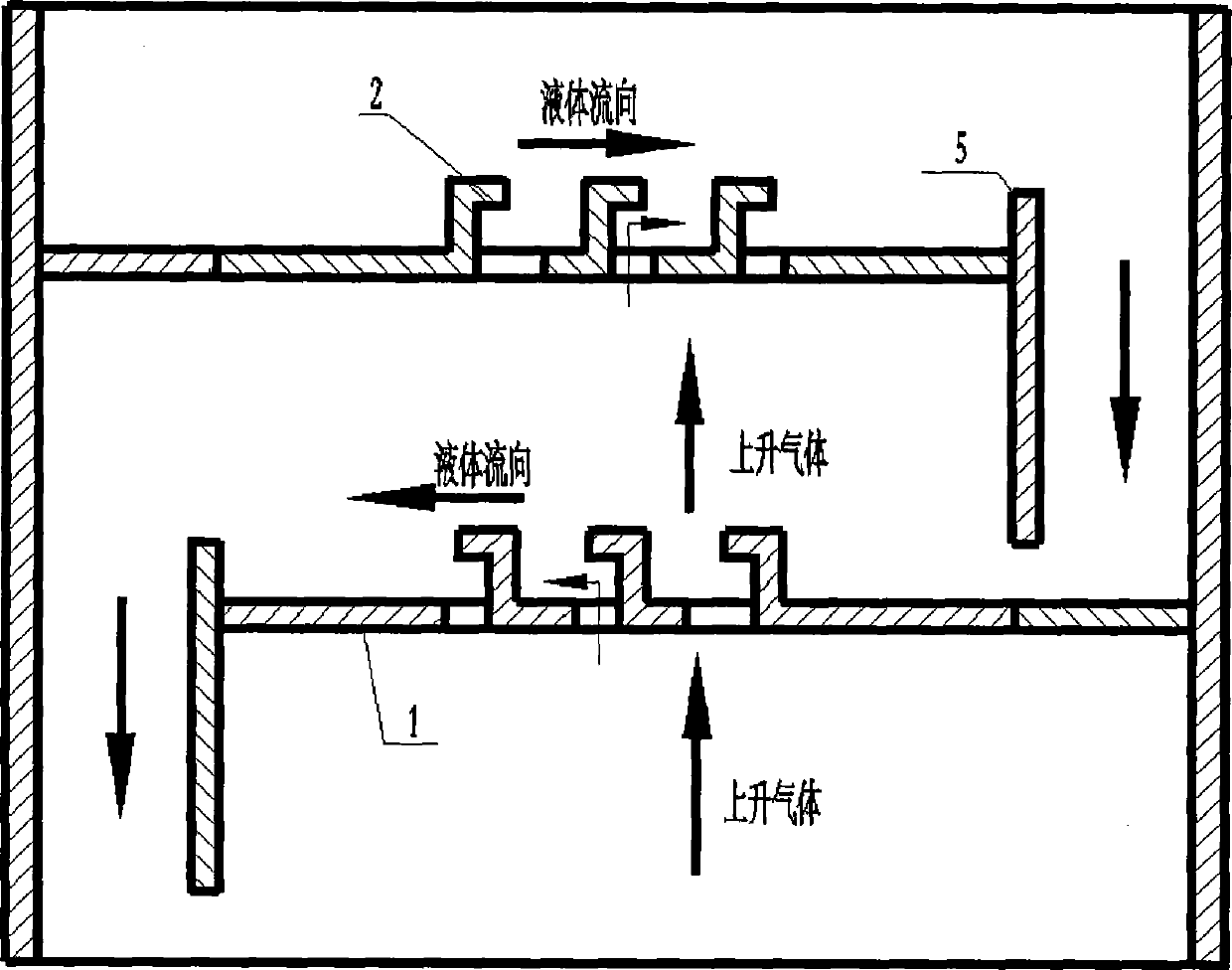
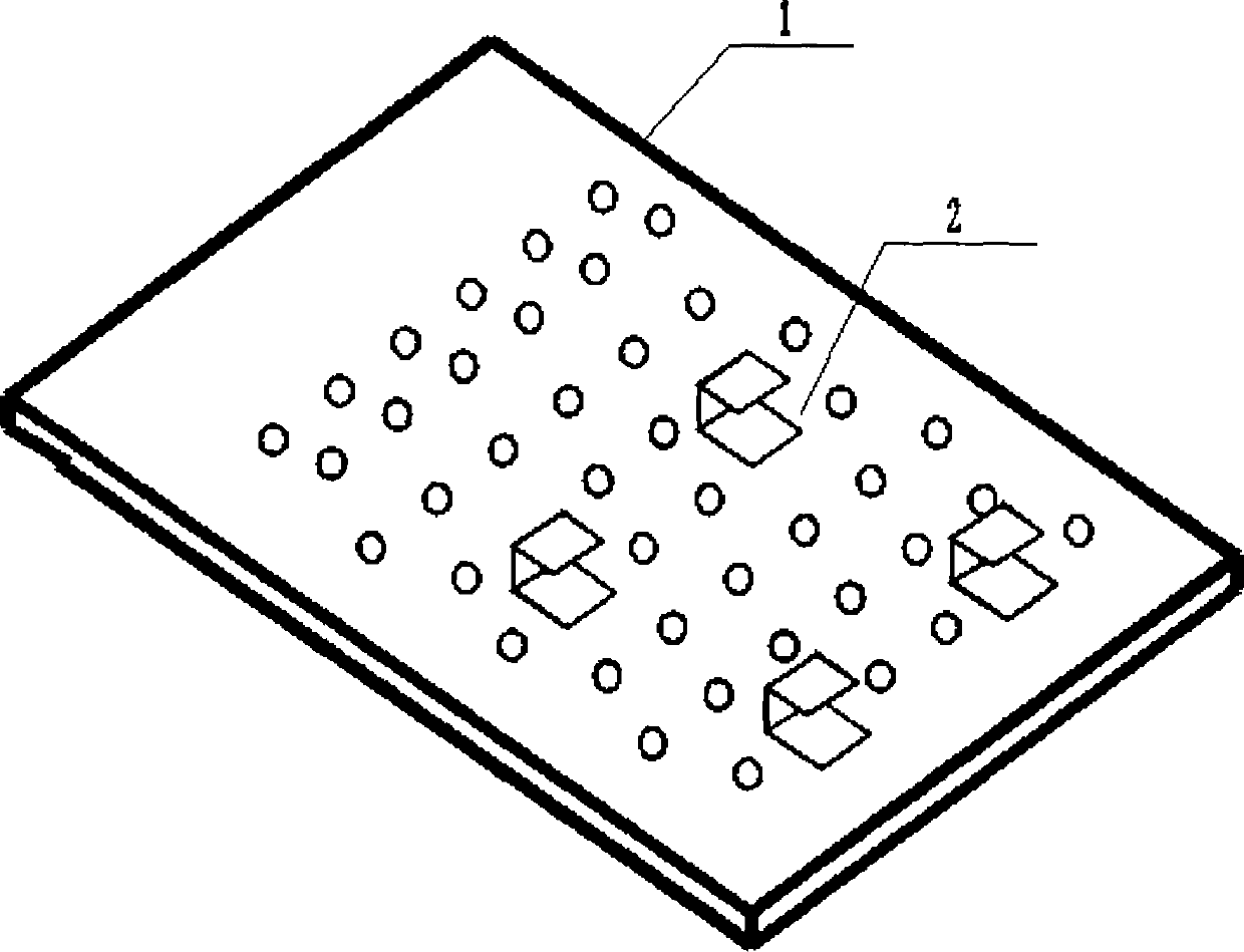
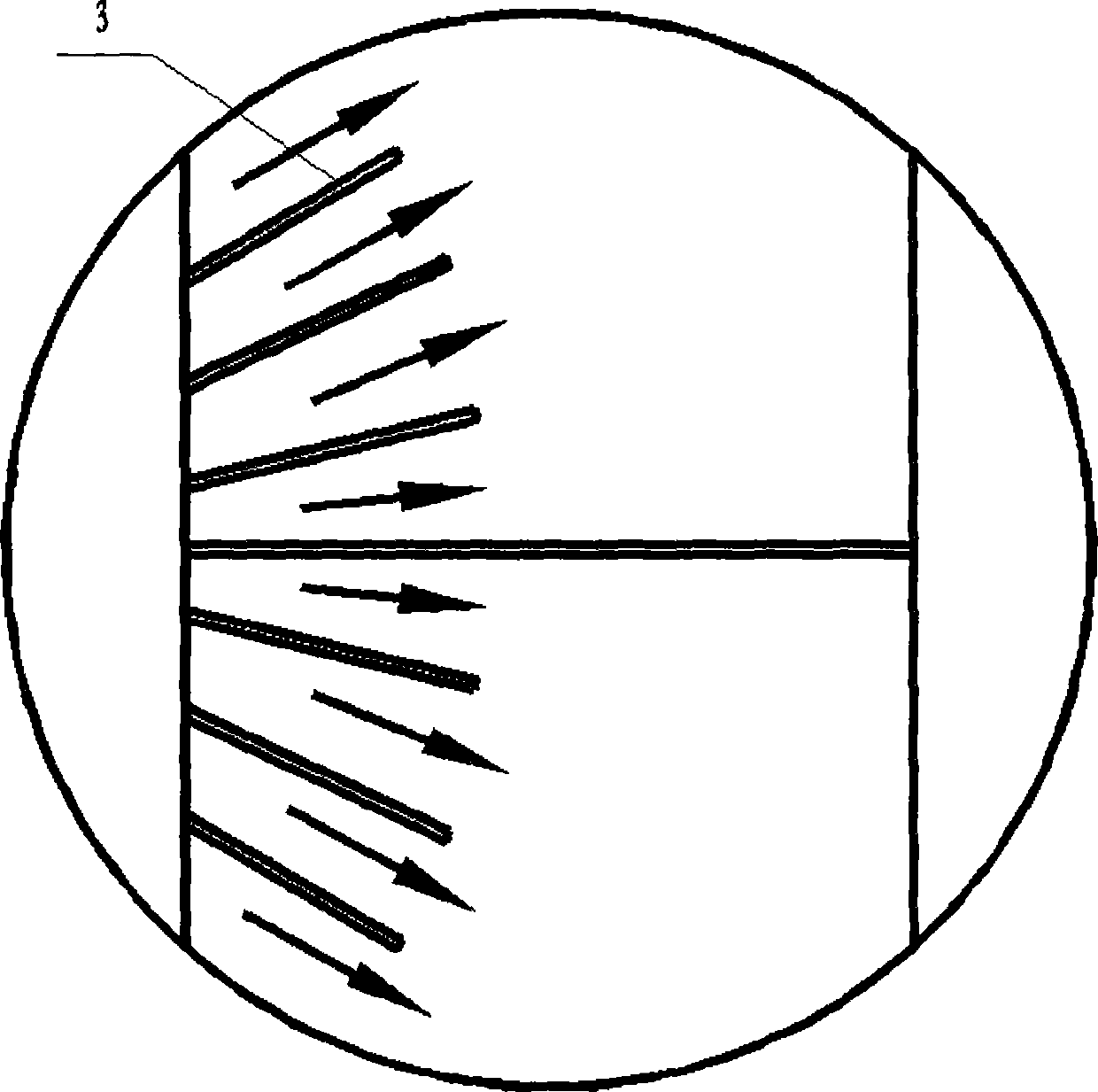
[0025] By the attachment Figure 1-6 It can be known that the gas-liquid guide tray of the present invention mainly includes guide holes, guide weirs, turbulence intensifiers, downcomer plates, and receiver trays. It is characterized in that the guide holes on the tray are bosses and guide The weir is set in the liquid phase inlet area, the turbulence intensifier is a special-shaped obstacle, and the downcomer plate is a broken line shaped downcomer plate. The specific working process of the tray of the present invention is as follows: the liquid phase flowing down from the upper tray flows down along the downcomer formed by the broken downcomer plate to form a certain height of liquid seal and ensure a certain accumulation in the downcomer. The liquid and liquid phase pass through the turbulence intensifier at the entrance of the liquid phase of the tray, destroying the la...


PUM


Abstract

The invention relates to a gas-liquid guiding column plate which is provided with a guide hole, guide weirs, turbulence intensifiers and a down-flow plate, wherein the guide hole in the column plate is a bump punched on the column plate, one edge, directly connected with the column plate, of the guide hole is vertical to the horizontal direction of the column plate while the other edge of the guide hole forms an included angle ranging from -30 degrees to 30 degrees with the horizontal direction of the column plate; the guide weirs on the column plate are a series of baffles vertical to the column plate, the height of each guide weir reaches or exceeds that of a bottom gap, and the width among the guide weirs is related to the strength of a liquid flow; the turbulence intensifier is arranged at the liquid phase inlet of each column plate, and each turbulence intensifier is an abnormal barrier integrally connected with the column plate; the down-flow plate on the column plate is a folded-line down-flow plate, so that a hole opening area and a gas-liquid transfer area are increased, and the liquid seal height of the down-flow pipe is increased. The column plate is high in mass transfer efficiency, great in production capacity, novel in structure and low in manufacturing cost, and can be widely applied to separating industries such as chemical engineering industry, oil refining industry, food industry, light industry and environmental industry.

Description

Technical field [0001] The invention relates to a gas-liquid guide tray with excellent performance, novel structure and low cost, and belongs to the field of vapor-liquid mass transfer equipment in a chemical separation process. Background technique [0002] Tower equipment is widely used in the operation of chemical units such as distillation, evaporation, absorption, desorption, drying and extraction. Column equipment involves a wide range of applications, including more applications in the rectification process. Tower equipment is suitable for pressurized, normal pressure and decompression systems; suitable for separating clean systems, and also suitable for solid deposition systems containing solid particles, easy to coke or fouling; tower equipment is also suitable for ideal or non-ideal, easy to rise Thousands of different separation systems and separation processes of different production requirements and scales such as foaming or non-foaming, low gas-liquid load or high ...

Claims


Application Information

Patent Timeline
IPC IPC(8): B01D3/22
Inventor 王宝华
Owner 河北化大科技有限公司
Learn More