
Flow guide filler

A technology of packing sheets and diversion holes, which is applied in chemical/physical/physicochemical processes, chemical instruments and methods, chemical/physical processes, etc., can solve the problem of increasing flow resistance between broken lines, reducing the liquid film area of ​​corrugated sheets, Affecting mass transfer efficiency and other issues, to achieve the effect of strengthening disturbance, realizing liquid film renewal, and improving mass transfer efficiency

Active Publication Date: 2014-04-02
河北化大科技有限公司
View PDF8 Cites 3 Cited by
  • Summary
  • Abstract
  • Description
  • Claims
  • Application Information

AI Technical Summary

Problems solved by technology

Nanjing University proposed a strong wallless flow structured packing (CN200810124793.2). The corrugated sheet of the packing is composed of N sections of short-distance corrugated channels, forming a zigzag corrugated channel. However, the corrugated sheet has been deflected many times. The flow resistance between the broken lines increases, and even causes the liquid film to fall off, affecting the mass transfer process
Tianjin University has developed an eccentric diversion window-type structured packing sheet and packing (CN201010577155.3). A diversion window is set on the crest or trough of the corrugated sheet. The axial direction of the diversion window has a certain angle with the direction of the corrugation inclination. To strengthen the lateral mixing in the filler, but opening windows on the corrugated sheet reduces the liquid film area on the corrugated sheet and affects the mass transfer efficiency

Method used


Image

  • Flow guide filler
  • Flow guide filler
  • Flow guide filler

Examples


Embodiment Construction

[0023] A diversion filler of the present invention will be further described in detail below in conjunction with the accompanying drawings.

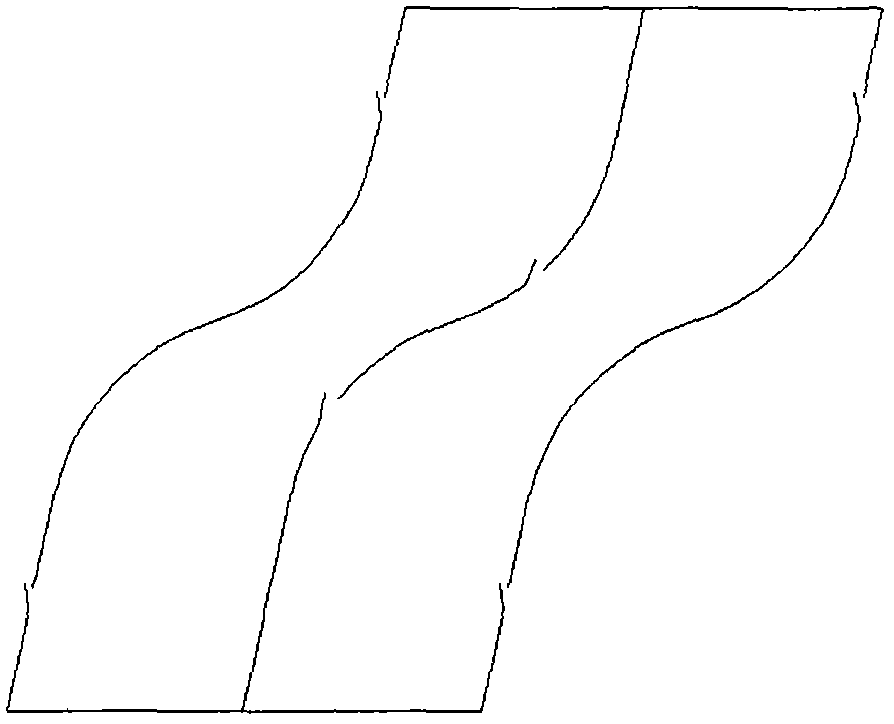
[0024] The structure of diversion packing is as figure 1 As shown, the surface of the filler sheet of the diversion filler is firstly treated with regular diamond particles, and the surface is roughened according to the regular vibration and rubbing in the direction of the liquid flow, so that the surface wettability of the filler sheet is increased. Then, according to the different specific surface area of ​​the filler, according to the requirements of peak height, corrugation inclination and tooth profile angle, the corrugated sheet is punched on a precision punching machine with a special abrasive tool. The middle of the corrugated ridgeline of the packing sheet is two symmetrically inverted curves The upper and lower ends are straight lines, the two curves are tangent, and the upper curve is tangent to the straight line of the upper ...


PUM


Abstract

The invention relates to a flow guide filler which is formed by stacking a plurality of layers of filler sheets, wherein two symmetrically-reversed curves are arranged in the middle parts of corrugated ridges of the filler sheets; the upper and lower ends of the corrugated ridges are straight lines; the two curves are tangent to each other; the curves at the upper end are tangent to the straight lines at the upper part; the curves at the lower end are tangent to the straight lines at the lower part; a height ratio of the curve parts of the corrugated ridges of the filler sheets to the straight line parts is 0.5-5; a series of rectangular, triangular and arc-shaped boss flow guide holes are punched in the filler sheets; the area of the boss flow guide holes punched in the filler sheets is 5-30% of the area of the filler sheets; regular diamond particles are adopted on the surfaces of the filler sheets, and vibrate and scour regularly in a liquid flow direction to perform surface roughening treatment; the filler is filled through combined filler discs with different inclination angles. The filler is good in surface film forming effect, so that an effective specific surface area is increased; gas-liquid phase perturbation is enhanced; meanwhile, a liquid surface updating rate is increased, so that gas-liquid mass transfer is full; mass transfer efficiency is greatly improved; the filler can be widely used in fields of petroleum, chemical industry, biology, pharmacy and environmental protection, and the like.

Description

technical field [0001] The invention relates to a novel gas-liquid diversion filler, which belongs to the field of gas-liquid mass transfer equipment in the chemical separation process. Background technique [0002] The tower is an important separation equipment, which is mostly used for the separation and purification of substances, and has a wide range of applications in the fields of petroleum, chemical industry, biology, pharmaceuticals, and environmental protection. The column is a balanced separation device, and the tray and packing provide the phase interface for interphase heat and mass transfer, which is the core component of the column. The core of the packed tower is the tower internal packing. The structure and performance of the packing directly affect the separation efficiency and investment cost of the packed tower. The development of packing with excellent performance is the key to the development and progress of the packed tower technology. Packing is mainl...

Claims


Application Information

Patent Timeline
Patent Type & Authority Applications(China)
IPC IPC(8): B01J19/32
Inventor 王宝华
Owner 河北化大科技有限公司
Learn More