Flue gas treatment device

A flue gas treatment and flue gas inlet technology, which is applied in the field of flue gas treatment, can solve problems such as poor flue gas flow uniformity, high side pressure drop of flue gas, and increased pressure head of the fan, so as to achieve good flue gas flow uniformity, flue gas Low air resistance and improved efficiency

Active Publication Date: 2014-04-02
SHANGHAI CLYDE BERGEMANN MACHINERY +1
View PDF6 Cites 13 Cited by
  • Summary
  • Abstract
  • Description
  • Claims
  • Application Information

AI Technical Summary

Problems solved by technology

However, the wet electrostatic precipitator and the flue gas heater are scattered in different locations, and each equipment exists independently, requiring a large footprint to arrange different equipment
[0007] In addition, each two-way transitional flue will generate a large pressure drop,

Method used


Image

  • Flue gas treatment device
  • Flue gas treatment device
  • Flue gas treatment device

Examples


Embodiment Construction

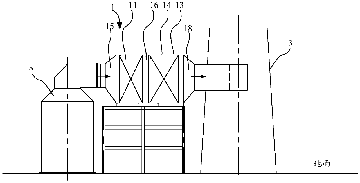
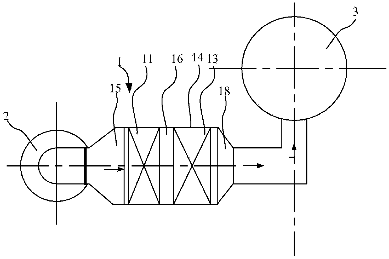
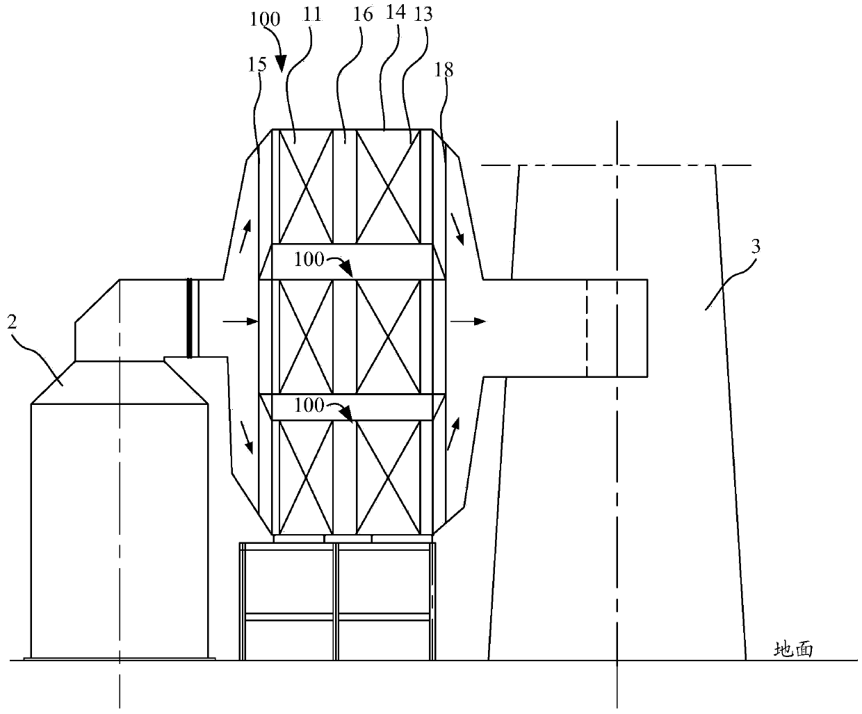
[0050] In the existing technology, several equipments such as wet electrostatic precipitator, mist eliminator and flue gas heater belong to different technical fields, are designed and supplied by different manufacturers, and the quantity is often different, and the arrangement form and size are difficult to match, so The current technology is that several different devices are mostly scattered in different positions, and there are several two-way transition flues in the middle. In this arrangement, each manufacturer can design independently without interfering with each other, so as to prevent the problem of buck-passing. The core of the invention is to disclose a flue gas treatment device, so as to realize the purpose of reducing the area occupied by the equipment and reducing the resistance of the flue gas.

[0051] Hereinafter, an embodiment will be described with reference to the drawings. In addition, the examples shown below do not limit the content of the invention des...


PUM


Abstract

An embodiment of the invention discloses a flue gas treatment device. According to the flue gas treatment device, a wet-type electric precipitator and a flue gas heater are integrated in an integrated flue shell, and the occupied area of the wet-type electric precipitator and the flue gas heater which are integrated together is smaller than the occupied area of the wet-type electric precipitator and the flue gas heater which are arranged separately. In addition, because the integrated flue shell does not have a bidirectional filtering flue, the flue gas flowing uniformity is high, flow equalizing orifice plates are not required to be arranged in the flue, resistance of flue gas is low, power consumption of a fan is reduced, and the efficiency of a power plant is improved.

Description

technical field [0001] The invention relates to the technical field of flue gas treatment, and more specifically, relates to a flue gas treatment device for a thermal power plant. Background technique [0002] The diversification of coal quality sources in thermal power plants makes the ash characteristics of coal quality changeable. Conventional flue gas treatment devices can only control dust emissions at 20-100mg / Nm 3 However, as people pay more attention to PM2.5 and environmental protection requirements become increasingly strict, the emission standards of thermal power plants are also required to reach 20-30mg / Nm 3 , the developed areas even have a 5mg / Nm emission similar to that of natural gas boilers 3 People began to apply wet electrostatic precipitators used in the chemical industry to thermal power plants to meet stricter dust emission requirements. [0003] Wet desulfurization technology can remove most of SO 2 , the flue gas after wet desulfurization is nearl...

Claims


Application Information

Patent Timeline
IPC IPC(8): F23J15/02F23J15/08
CPCB03C3/017B03C3/025B03C3/16B01D2257/302B01D2258/0283B01D53/323B01D53/343B01D53/40B01D53/501B01D53/64B01D53/75B01D2257/60B03C3/019B03C3/82
Inventor 高新民吴梅康明余希之
Owner SHANGHAI CLYDE BERGEMANN MACHINERY
Why Eureka
Try Eureka