Front end device of portable ultrasound system

An ultrasonic system, a portable technology, applied in measuring devices, sound wave re-radiation, radio wave measurement systems, etc., can solve the problem of undesigned transmission circuit filter part, etc., and achieve low power consumption, easy manufacture, and reduced volume.

Inactive Publication Date: 2014-04-02
SHENZHEN INST OF ADVANCED TECH
View PDF4 Cites 14 Cited by
  • Summary
  • Abstract
  • Description
  • Claims
  • Application Information

AI Technical Summary

Problems solved by technology

In this scheme, the transmitting circuit and the filtering part of the ultrasonic echo are not designed to improve the signal-to-noise ratio of the echo signal

Method used


Image

  • Front end device of portable ultrasound system
  • Front end device of portable ultrasound system
  • Front end device of portable ultrasound system

Examples


Embodiment Construction

[0025] The present invention will be described in further detail below in conjunction with the accompanying drawings and specific embodiments.

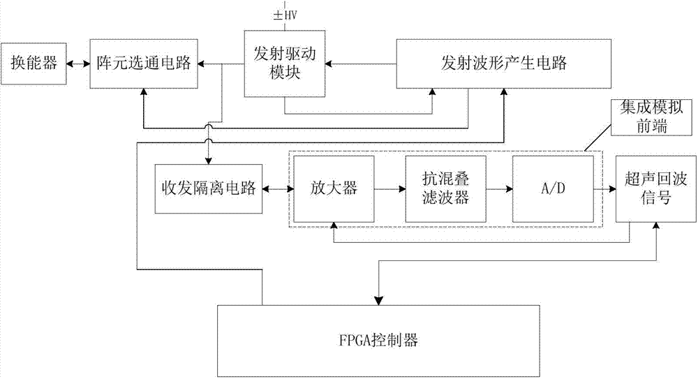
[0026] Such as figure 2 As shown, the present invention provides a front-end device of a portable ultrasound system, including an integrated analog front-end, an FPGA controller, a transmission drive circuit, an array element gating circuit, and a transducer.

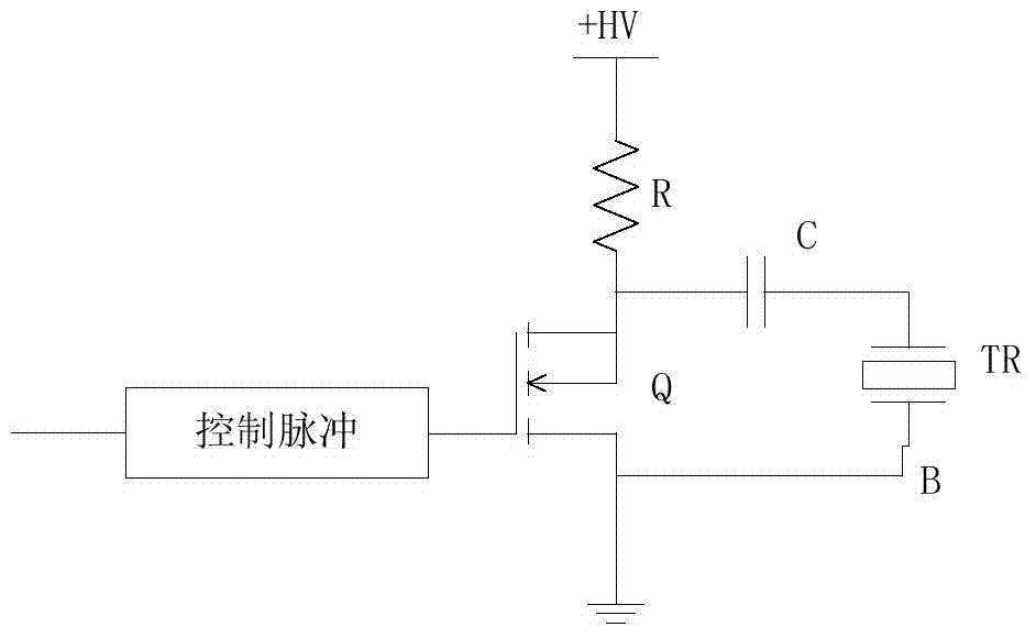
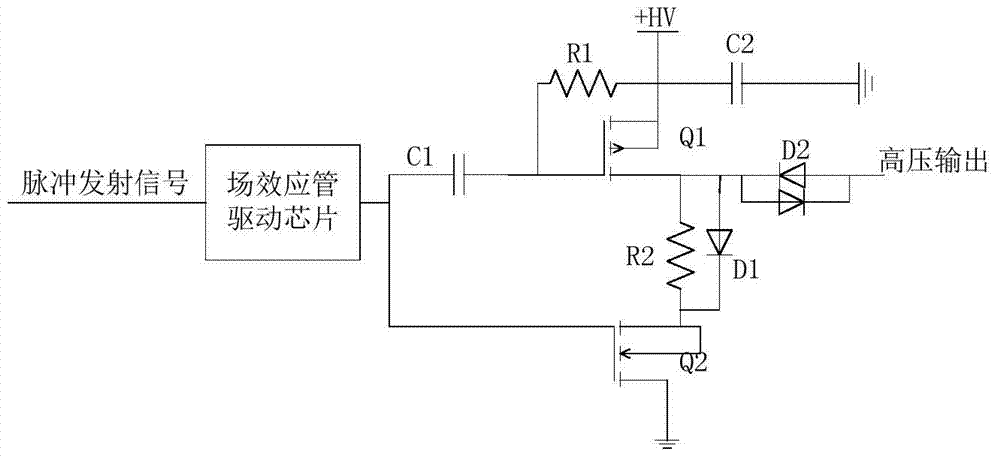
[0027] The FPGA controller is used for transmitting the drive circuit and integrated analog front-end control; the integrated analog front-end is used for receiving the ultrasonic echo signal transmitted by the array element gating circuit and performing pre-amplification, variable gain amplification, filtering and analog-to-digital conversion; The transmitting driving circuit is used for receiving the timing control signal of the FPGA controller, and transmitting the transmitting signal to the transducer through the element gating circuit.

[0028] Among them, the FPGA contr...


PUM


Abstract

The invention discloses a front end device of a portable ultrasound system, which comprises an integrated analog front end, an FPGA (Field-Programmable Gate Array) controller, a transmitting drive circuit, an array element gating circuit and a transducer, wherein the transmitting drive circuit is used for receiving time sequence control signals of the FPGA controller and transmitting transmission signals to the transducer via the array element gating circuit, the transmitting drive circuit comprises a transmitted waveform generating circuit and a transmitting drive module, and the transmitted waveform generating circuit receives the time sequence control signals of the FPGA controller and transmits the signals to the transmitting drive module. The device adopts the transmitting drive module to avoid the charge/discharge circuit of an capacitor from passing a field effect pipe, so as to play a certain role of protecting the field effect pipe; the circuit of a TGC part is realized via the integrated analog front end, therefore, the volume of the system is greatly reduced, and portable equipment is easy to manufacture; the device has a power saving mode, thereby being low in power consumption.

Description

technical field [0001] The invention relates to the technical field of ultrasonic imaging, in particular to a front-end device of a portable ultrasonic system. Background technique [0002] The front-end device of an existing ultrasonic imaging system includes two parts: a transmitting part for emitting high-voltage pulses to excite a transducer to generate ultrasonic waves and a receiving part for receiving ultrasonic echo signals. Such as figure 1 As shown, Q is a switch tube, generally a MOS tube is used, and the on-off of Q is controlled by a control signal. When Q is turned on, a negative high-voltage pulse will be generated at point B, and this pulse will be loaded on both ends of the transducer to excite the probe to form ultrasonic waves. In the above circuit, the capacitor C is charged and then discharged, and the discharge circuit directly passes through Q, which has a great impact on the working efficiency and service life of the switching device. [0003] The ...

Claims


Application Information

Patent Timeline
Patent Type & Authority Applications(China)
IPC IPC(8): G01S7/526G01S7/529
CPCG01S7/52025G01S7/52033G01S15/8906
Inventor 李慧慧文夏清周永进王磊
Owner SHENZHEN INST OF ADVANCED TECH
Why Eureka
Try Eureka