Optical imaging method and system for large-scale high-resolution remote sensing camera

An optical imaging system and high-resolution technology, applied in the field of optical imaging systems, can solve the problems that it is difficult to meet the requirements of large field of view and high resolution at the same time, achieve high resolution and reduce spherical aberration

Inactive Publication Date: 2014-04-02
苏州信沃特光电科技有限公司
View PDF5 Cites 17 Cited by
  • Summary
  • Abstract
  • Description
  • Claims
  • Application Information

AI Technical Summary

Problems solved by technology

Therefore, it is difficult to meet the requirements of large field of view and high resolution for modern remote sensor imaging systems at the same time using traditional design methods

Method used


Image

  • Optical imaging method and system for large-scale high-resolution remote sensing camera
  • Optical imaging method and system for large-scale high-resolution remote sensing camera
  • Optical imaging method and system for large-scale high-resolution remote sensing camera

Examples


Embodiment 1

[0030] The technical solution of this embodiment is to provide a multi-scale, large field of view, and high-resolution optical imaging system for large-scale high-resolution remote sensing cameras. / #=4.0, the full field of view is 120 degrees.

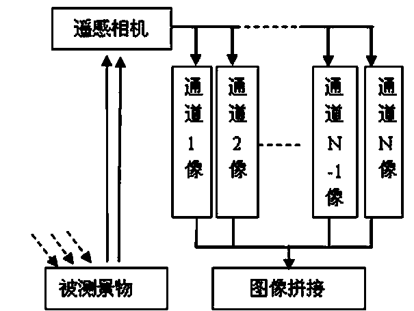
[0031] See attached figure 1 , which is a schematic diagram of the working principle of the multi-scale optical system for large-scale high-resolution remote sensing cameras provided by the present invention; The reflected light of sunlight, after passing through the multi-scale optical system, forms an optical image on the photosensitive surface of each channel detector, and outputs the captured target image after being collected by electronic circuits and image processing, so as to obtain the height of the target scene in a large range of ground objects. resolution image.

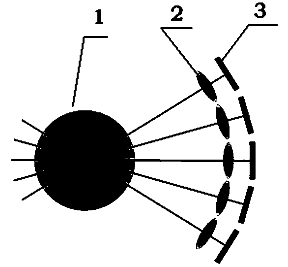
[0032] See attached figure 2 , which is a structural schematic diagram of the optical imaging system for large-scale high-resolution remote sensing cameras p...

Embodiment 2

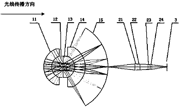
[0042] In this embodiment, the working wavelength range is 0.72 μm to 1.0 μm, the system F number is F / #=4.0, and the full field of view is 120 degrees. For the structure of the optical system and the imaging optical path, please refer to the attached figure 2 And attached image 3 .

[0043] The remaining parameters of the optical imaging system are as follows: the focal lengths of the front objective lens and the microlens single-channel optical imaging system are 70mm and 20mm respectively, along the light direction, the meniscus spherical negative lens 11, the plano-convex spherical positive lens 12, and the plano-convex spherical positive lens 13. The radius of curvature of meniscus spherical negative lens 14, intermediate image surface 15, spherical negative lens 21, spherical positive lens 22, spherical positive lens 23, and spherical negative lens 24 are respectively 31.12mm, 18.43mm, Infinity, -19.13 mm, -35.55mm, -72.01mm, 12.99mm, 5.87mm, -53.36mm, 391.52mm, -3.08...


PUM


Abstract

The invention relates to an optical imaging method and an optical imaging system for a large-scale high-resolution remote sensing camera. A micro lens array is arranged between a front object lens and a focal plane of a detector. The front object lens adopts a concentric and symmetrical spherical lens structure to obtain a large-field scene. Each passage of the micro lens array consists of a group of separated doublet lenses. The separated doublet lenses are used for realizing fine aberration correction within a small field range of the passages undertaken by the separated doublet lenses to form a plurality of independent imaging passages, so as to image all information in the entire field onto the focal plane of the detector without any loss and obtain high-resolution images with diffraction limit performance at all positions in the large field. The optical imaging system for the large-scale high-resolution remote sensing camera has the characteristics that since an pure transmission-type optical structure is adopted, the structure is simple and compact, the system is suitable for the entire visible light working wavelength range, the view field is large, the image quality of the entire view field is uniform, the imaging performance is excellent, the cost is low and the like. The space resolution of the multi-scale optical imaging system provided by the invention is not limited by the view field and the multi-scale optical imaging system is suitable for remote sensing cameras for earth observation and general survey.

Description

technical field [0001] The invention relates to an optical imaging system for a large-scale high-resolution remote sensing camera, in particular to a multi-scale structure, refraction type, working in the entire visible light band, large field of view, and high-resolution optical imaging methods and systems. Background technique [0002] With the continuous development of space exploration and earth observation, the field of view and resolution requirements of imaging systems are getting higher and higher. In order to achieve real-time acquisition of high-resolution optical images within a large field of view, large-scale high-resolution cameras have always been the difficulty and focus of research. [0003] With traditional imaging methods and systems, large field of view and high resolution are mutually restricted. When the working wavelength is fixed, the only way to improve the resolution of the system is to increase the system aperture. However, the large field of vie...

Claims


Application Information

Patent Timeline
Patent Type & Authority Applications(China)
IPC IPC(8): G02B27/58G01C11/02
Inventor 季轶群王岩
Owner 苏州信沃特光电科技有限公司
Why Eureka
Try Eureka