

Rotating electrical machine and electric power steering system using the same
A technology of rotating electrical machines and electric drives, applied in electric steering mechanisms, synchronous motors with stationary armatures and rotating magnets, electromechanical devices, etc. Problems such as the stator slot fullness ratio of the motor, to achieve the effects of high torque ripple, reduced cogging torque, and high torque
- Summary
- Abstract
- Description
- Claims
- Application Information
AI Technical Summary
Problems solved by technology
Method used
Image

Examples
Embodiment 1
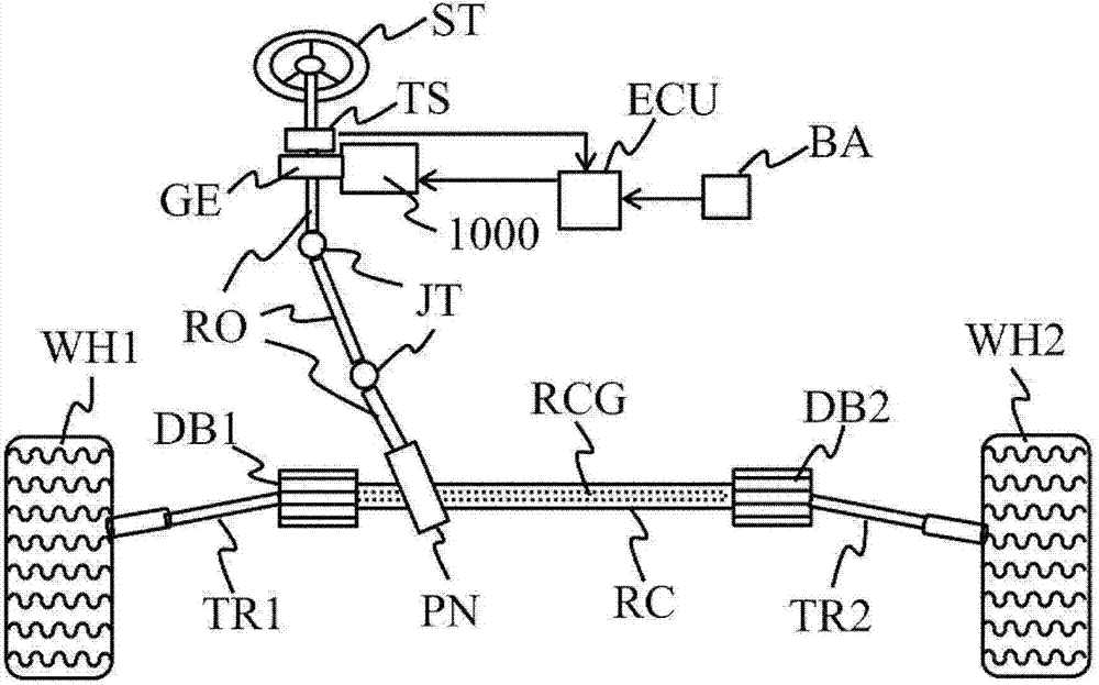
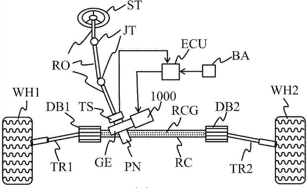
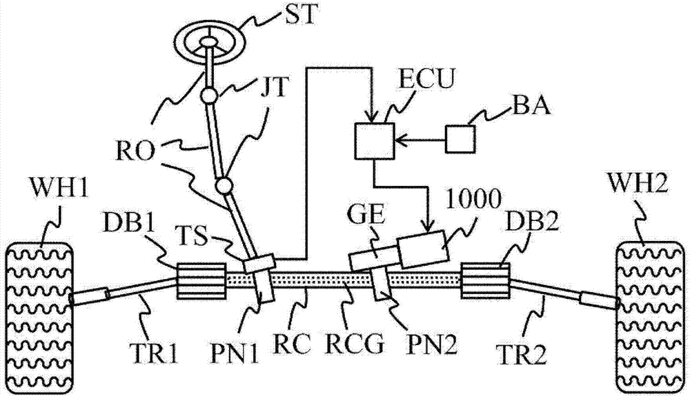
[0035] The first embodiment of the present invention will be described. First, use figure 1 ~3 explains the operation principle related to the electric power steering of this embodiment. The electric power steering system of this embodiment has: an on-vehicle power supply; a control device that converts DC power supplied from the on-vehicle power supply via wiring into multi-phase AC power, and controls the output thereof according to torque applied to the steering wheel; and An electric power steering motor that is driven by AC power supplied from the control device and outputs steering assist torque, wherein the electric power steering motor has: a frame; a stator fixed to the frame; The rotor arranged opposite to the stator has a stator core and multi-phase stator coils incorporated in the stator core. The stator core is composed of an annular core yoke (back core) and a radial It consists of a plurality of protruding tooth cores, a groove is formed between adjacent tooth...
Embodiment 2
[0053] use Figure 7 A second embodiment of the present invention will be described. Figure 7 (a) shows the assembled state of the stator core 200, the bobbin 300, and the stator coil 400. Here, the stator coil 400 adopts a square wire or a flat wire. Square or flat wires are suitable for winding stator coils neatly, and can be expected to improve the slot fill factor. In addition, compared with the round wire, the coil is not easy to move in the slot after winding, and it is also more convenient to manufacture. Figure 7 (b) is a diagram showing continuous winding of adjacent in-phase coils. Here too, the stator coil is continuously wound around two teeth from the winding start end 401 until the winding end 402 is reached. Also, similarly to the first embodiment, when the number of turns of one coil is n, the number of turns of the adjacent same-phase coil is an integer number more than n turns or an integer number less than n turns. In addition, it is more preferable t...
Embodiment 3
[0055] use Figure 8 Embodiment 3 of the present invention will be described. Figure 8 (a) shows the assembled state of the stator core 200, the bobbin 300, and the stator coil 400. Figure 8 (b) is a diagram showing continuous winding of adjacent in-phase coils. The stator coil starts to wind from the winding starting end 401. After winding n turns, it spans to the adjacent teeth, and continuously winds m turns on the adjacent teeth in the opposite direction of winding, where m is more than n turns 0.5 turns or 0.5 turns less than n turns. where n and m are integer values. In this way, the space of the slot can be effectively used, the fullness of the slot can be improved, and the degree of freedom of design can be improved. As in the first and second embodiments, since fine selection of the number of turns is possible, the degree of freedom in design can be greatly improved. In addition, in this case, since the winding start end and the winding end protrude opposite to...
PUM
 Abstract
Description
Claims
Application Information