FPGA (field programmable gate array)-based permanent magnet synchronous motor current loop bandwidth expansion device

A permanent magnet synchronous motor and bandwidth expansion technology, which is applied in the control of electromechanical transmission, control of generators, motor generator control, etc., can solve low-delay bandwidth, low bandwidth, and delay of permanent magnet synchronous motor current control loop To achieve the effect of improving the bandwidth of the current loop, improving the overall performance, and optimizing the timing of the current control

Active Publication Date: 2014-04-02
HUAZHONG UNIV OF SCI & TECH
View PDF2 Cites 23 Cited by
  • Summary
  • Abstract
  • Description
  • Claims
  • Application Information

AI Technical Summary

Problems solved by technology

[0005] The purpose of the present invention is to propose a low-delay, high-bandwidth FPGA-based permanent magnet synchronous motor current

Method used


Image

  • FPGA (field programmable gate array)-based permanent magnet synchronous motor current loop bandwidth expansion device
  • FPGA (field programmable gate array)-based permanent magnet synchronous motor current loop bandwidth expansion device
  • FPGA (field programmable gate array)-based permanent magnet synchronous motor current loop bandwidth expansion device

Examples


Embodiment Construction

[0033] In order to make the object, technical solution and advantages of the present invention more clear, the present invention will be further described in detail below in conjunction with the accompanying drawings and embodiments. It should be understood that the specific embodiments described here are only used to explain the present invention, not to limit the present invention. In addition, the technical features involved in the various embodiments of the present invention described below can be combined with each other as long as they do not constitute a conflict with each other.

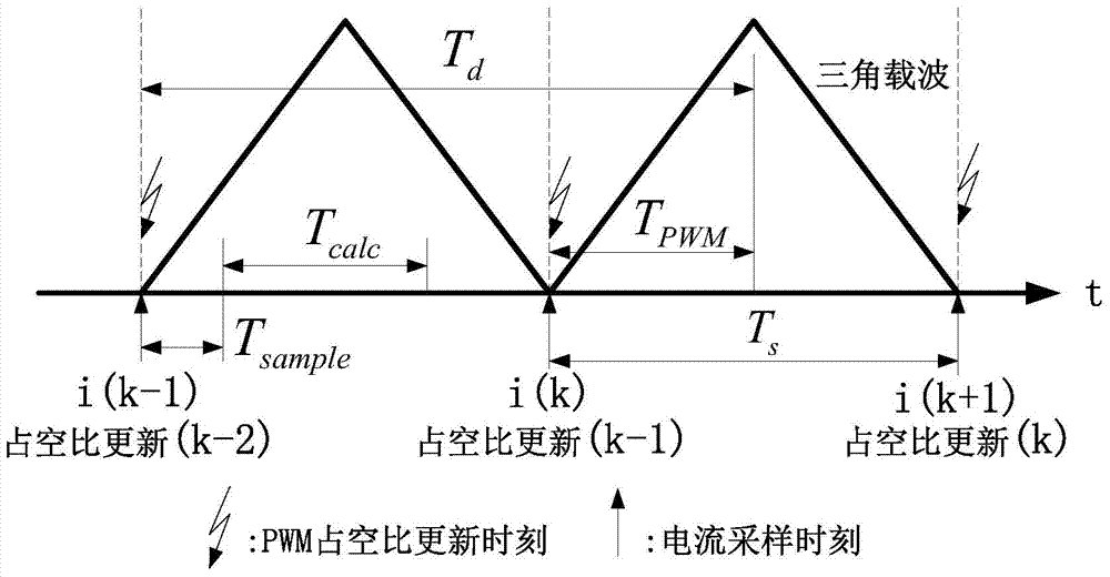
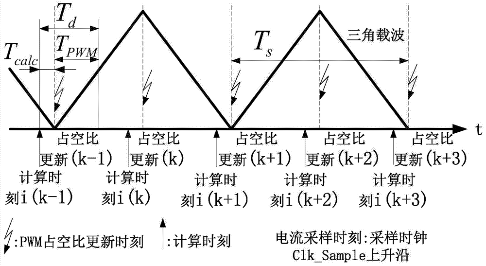
[0034] Such as figure 2 shown, for figure 2 For the current loop control timing diagram of the permanent magnet synchronous motor proposed by the present invention, two vector control calculations and two PWM outputs are performed in one current control cycle, and the current sampling time is adjusted to reduce the delay of the current control loop. Specifically, PWM output is performed a...


PUM


Abstract

The invention discloses an FPGA (field programmable gate array)-based permanent magnet synchronous motor current loop bandwidth expansion device. The device comprises a current sampling module, a Clark conversion module, a Park conversion module, a PI (proportional-integral) module, an iPark conversion module, an SVPWM (space vector pulse width modulation) module and a time sequence control module, wherein the current sampling module is used for reading current sampling values ia and ib of a phase A and a phase B; the Clark conversion module is used for converting the ia and the ib into an alpha-beta coordinate system to obtain ialpha and ibeta, the Park conversion module is used for converting the ialpha and the ibeta into a d-q coordinate system to obtain a direct axis current id and a quadrature axis current iq; the PI module is used for comparing a command current with feedback currents id and iq to obtain a current deviation value, and computing to obtain command voltages Vd and Vq in the d-axis and the q-axis; the iPark conversion module is used for converting the Vd and the Vq into an alpha-beta coordinate system to obtain Valpha and Vbeta; the SVPWM module is used for calculating a three-phase PWM duty ratio according to the Valpha and the Vbeta, and generating six paths of PWM waveforms; the time sequence control module is used for starting or closing a corresponding module according to a current control time sequence, and completing the control of the current of a permanent magnet synchronous motor. According to the device, the delay in a current control loop is greatly reduced through the optimization of a control time sequence and the design of an FPGA-based current controller, so that the bandwidth of the current loop is improved.

Description

technical field [0001] The invention belongs to the technical field of motor control, and more specifically relates to an FPGA-based permanent magnet synchronous motor current loop bandwidth expansion device. Background technique [0002] Permanent magnet synchronous motor control generally includes three control loops: position loop, speed loop and current loop. Among them, the current loop is the innermost layer of the whole system, and its control performance directly affects the response performance of the speed loop and position loop of the servo system. [0003] In the permanent magnet synchronous motor control system, the current controller first samples the motor phase current, and then calculates the reference voltage vector (V α , V β ), and finally use the SVPWM modulation method to calculate the PWM duty cycle and output the PWM wave to control the opening and closing of the IPM or IGBT to achieve the purpose of controlling the motor current. Among them, the m...

Claims


Application Information

Patent Timeline
IPC IPC(8): H02P21/00
Inventor 宋宝叶伯生苏玲宏郑世祺陈天航唐小琦周向东代攀唐玉枝
Owner HUAZHONG UNIV OF SCI & TECH
Why Eureka
Try Eureka