Filter at front end of outer part of household appliance for improving power spectral density of power line communication

A technology of power spectral density and front-end filter, applied in the direction of electrical components, multi-terminal pair network, distribution line transmission system, etc. Weakness and other problems, to achieve the effect of high reliability and stability, convenient connection and simple structure

Active Publication Date: 2014-04-02
陕西翌鑫科技发展有限公司
View PDF5 Cites 7 Cited by
  • Summary
  • Abstract
  • Description
  • Claims
  • Application Information

AI Technical Summary

Problems solved by technology

At present, household appliances tend to be powered by high-frequency switching power supplies, such as: notebook computers, desktop computers, LED TVs, air conditioners, LED lamps, etc. Due to the use of high-frequency switching technology for these household appliances, their Electro Magnetic Interference (EMI) problems It is more serious. Although the front end of the equipment is designed with an EMI filter, the filter design is generally within 30MHz. If it exceeds 30MHz, large differential mode and common mode noise will be transmitted into the grid environment. These ultra-high frequency EMI signals will The signal strength of the power cat is reduced, that is, the power spectral density is weakened, and the Ethernet communication is slowed down or even interrupted

Method used


Image

  • Filter at front end of outer part of household appliance for improving power spectral density of power line communication
  • Filter at front end of outer part of household appliance for improving power spectral density of power line communication

Examples


Embodiment Construction

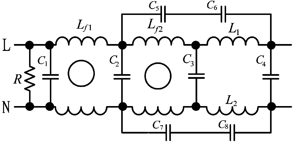
[0027] like figure 1 As shown, the present invention includes a bleeder resistor R, a common mode choke coil L f1 and L f2 , X capacitance C 1 、C 2 、C 3 and C 4 , differential mode inductance L 1 and L 2 , and the high voltage pulse absorbing capacitor C 5 、C 6 、C 7 and C 8 ; The common mode choke L f1 and L f2 Both have an annular magnetic core and two coils wound on the annular magnetic core, the bleeder resistor R, X capacitor C 1 , X capacitance C 2 , X capacitance C 3 and X capacitor C 4 sequentially connected in parallel between the neutral line L and the live line N of the power input line, the common mode choke coil L f1 The two coils are connected in series with the X capacitor C 1 and X capacitor C 2 between the neutral line L and the live line N, the common mode choke L f2 The two coils are connected in series with the X capacitor C 2 and X capacitor C 3 between the neutral line L and the live line N, the differential mode inductor L 1 in serie...


PUM


Abstract

The invention discloses a filter at the front end of the outer part of a household appliance for improving the power spectral density of power line communication. The filter comprises a bleeder resistor R, common mode chokes Lf1 and Lf2, X capacitors C1, C2, C3 and C4, difference mode inductors L1 and L2, and high-voltage pulse absorbing capacitors C5, C6, C7 and C8, wherein the bleeder resistor R and the X capacitors C1, C2, C3 and C4 are connected between a null line and a live wire in parallel in sequence, two coils of the common mode chokes Lf1 are connected to a null line and a live wire between the capacitor C1 and the capacitor C2 in series respectively, two coils of the common mode chokes Lf2 are connected to a null line and a live wire between the capacitor C2 and the capacitor C3 in series respectively, the difference mode inductors L1 and L2 are connected to a null line and a live wire between the X capacitor C3 and the X capacitor C4 in series respectively, the high-voltage pulse absorbing capacitors C5 and C6 are connected in series, and the high-voltage pulse absorbing capacitors C7 and C8 are connected in series. The filter can be used for inhibiting an EMI (electro magnetic interference) signal conducted by the household appliance into a power grid, and blocking a power line carrier signal from being lost in the household appliance, so that the power spectral density of the power line communication is improved.

Description

technical field [0001] The invention relates to the technical field of power line carrier communication, in particular to an external front-end filter of a household appliance for improving the power spectral density of a power cat. Background technique [0002] Power cat is also called PLC (Power Line Communication, PLC). The PLC industry has been developed abroad for many years, and now foreign developed countries have basically popularized the use of power carrier equipment (that is, "power cat"). The real application of power carrier technology to civilian use in China originated around 2008. The digital Internet TV (IPTV) launched during the Olympic Games has provided a hotbed for the development of power carrier equipment. After 2010, with the popularization of home broadband, more and more network applications have been applied, and domestic PLC manufacturers have also sprung up. [0003] One of the difficulties faced by the power cat in the application process is th...

Claims


Application Information

Patent Timeline
Patent Type & Authority Applications(China)
IPC IPC(8): H03H7/01H04B3/54
Inventor 康海峰姬军鹏
Owner 陕西翌鑫科技发展有限公司
Why Eureka
Try Eureka