TDD (time division duplexing) system-based fault diagnosis device

A fault diagnosis device and fault technology, which is applied in the field of communication, can solve the problems of increased monitoring difficulty, increased circuit, increased monitoring link and design, etc., to achieve the effects of saving area, improving recognition, and facilitating positioning or troubleshooting

Active Publication Date: 2014-04-02
DATANG MOBILE COMM EQUIP CO LTD
View PDF4 Cites 3 Cited by
  • Summary
  • Abstract
  • Description
  • Claims
  • Application Information

AI Technical Summary

Problems solved by technology

However, this method has problems such as poor granularity and low module fault identification ability. The judgment of on-site faults, as well as the positioning and disassembly of production or repair will all reduce the diagnostic efficiency.
In particular, once the RF connector has a reliability problem, it may be difficult to verify (often unboxing and unpacking, the RF connector may return to normal), resulting in losses such as repeated disassembly and assembly, and back and forth repairs
[0005] In order to overcome the above problems such as poor granularity and low module fault identification ability, there is another method for diagnosing the reliability of RF connectors, referring to the common power amplifier power coupling monitoring method of the whole machine, simply copying the power amplifier power coupling monitoring module Adding to the transceiver board, there are many problems in this method, such as the transmission signal is too small, which makes it more difficult to monitor; increasing the monitoring link and design, resulting in an increase in cost and circuit area, which is not conducive to reducing cost and compact equipment; adding circuits, lead to increased power consumption, etc.

Method used


Image

  • TDD (time division duplexing) system-based fault diagnosis device
  • TDD (time division duplexing) system-based fault diagnosis device
  • TDD (time division duplexing) system-based fault diagnosis device

Examples


Embodiment Construction

[0029] In order to make the above objects, features and advantages of the present application more obvious and comprehensible, the present application will be further described in detail below in conjunction with the accompanying drawings and specific implementation methods.

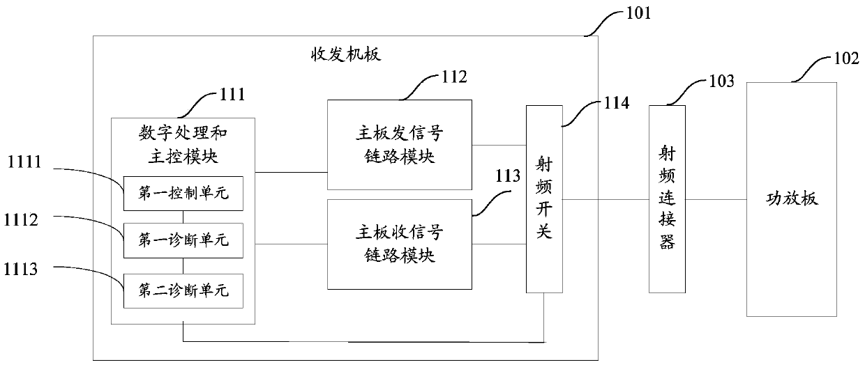
[0030] refer to figure 1 , which shows a structural diagram of an embodiment of a fault diagnosis device based on a time division duplex TDD system in the present application, which may specifically include a transceiver board 101, a power amplifier board 102, and a power amplifier board 102 connected between the transceiver board 101 and the power amplifier board 102 RF connector 103;

[0031] Wherein, the transceiver board 101 may specifically include: a digital processing and main control module 111, a mainboard signaling link module 112, a mainboard receiving signal link module 113 and a radio frequency switch 114;

[0032] Wherein, the radio frequency switch 114 is respectively connected with the d...


PUM


Abstract

The invention provides a TDD (time division duplexing) system-based fault diagnosis device. The TDD system-based fault diagnosis device comprises a transceiver plate, a power amplifier plate and a radio frequency connector connected between the transceiver plate and the power amplifier plate; the TDD system-based fault diagnosis device is characterized in that the transceiver plate comprises a digital processing and main control module, a main board signal sending link module, a main board signal receiving link module and a radio frequency switch, wherein the radio frequency switch is used for opening and closing an sending channel and a receiving channel of the transceiver plate according to a control signal from the digital processing and main control module; the digital processing and main control module is used for monitoring the signal power of the receiving channel under the condition that RRU (radio remote unit) equipment has a fault and judging whether the difference value between an estimated value of full link signal power and a signal power monitoring value of the receiving channel exceeds a threshold value or not. The TDD system-based fault diagnosis device facilitates the remote or unpacking positioning or fault removing of an equipment fault, and the area, power consumption and cost occupied by a detection link can be saved.

Description

technical field [0001] The present application relates to the technical field of communication, in particular to a fault diagnosis device based on a TDD system. Background technique [0002] At present, with the promotion of the TDD (Time Division Duplexing) system, the bandwidth of the base station is increasing day by day, and the power level of the power amplifier of the base station equipment is increasing day by day, thus affecting the reliability, stability, high performance and maintainability of the base station equipment And other performance, put forward higher requirements and challenges. [0003] Considering the performance of heat dissipation, key indicators, frequency band characteristics, etc., a mainstream architecture of the existing RRU (Remote Radio Unit, Radio Remote Unit) equipment is to separate the transceiver from the middle horizontally, which usually separates the RF power amplifier and the low-frequency power amplifier. The noise amplifier is inte...

Claims


Application Information

Patent Timeline
Patent Type & Authority Applications(China)
IPC IPC(8): H04W24/04
CPCY02B60/50Y02D30/70
Inventor 伍坚陈茂云黄腾刘甜
Owner DATANG MOBILE COMM EQUIP CO LTD
Why Eureka
Try Eureka