Aortic valve stent capable of preventing perivalvular leakage

An aorta and valve technology, applied in the field of medical devices, can solve problems such as valve performance decline, increase sheath diameter, and difficulty in sheathing, achieve good compliance and shape memory performance, reduce the risk of vascular complications, and avoid valve stents deformation effect

Active Publication Date: 2014-04-09
NINGBO JENSCARE BIOTECHNOLOGY CO LTD
View PDF11 Cites 35 Cited by
  • Summary
  • Abstract
  • Description
  • Claims
  • Application Information

AI Technical Summary

Problems solved by technology

When the compliance of the stent is insufficient, the support force of the stent is high, and the valve stent maintains a circular design after release. Although the hemodynamics and opening and closing functions of the valve are guaranteed, there will be paravalvular leakage in the tissue ring recess; when the stent complies When the stability is good, the support force of the stent is low, and the valve stent conforms to the contour of the tissue ring after being released. At this time, the valve becomes irregular passively, and the protruding part of the tissue ring will deform the valve, and the performance of the valve will decline; 2. The sealing in the existing design The unit cannot automatically fill the concavity of the patient's tissue ring and conform to its convexity; third, the partially sealed unit in the existing design will cause difficulty in sheathing, increase the diameter of the sheath tube, and may cause serious vascular complications after use; Water-swellable materials are used to prevent paravalvular leaks where there may be an uncontrollable rate of swelling and a risk of leakage

Method used


Image

  • Aortic valve stent capable of preventing perivalvular leakage
  • Aortic valve stent capable of preventing perivalvular leakage
  • Aortic valve stent capable of preventing perivalvular leakage

Examples


specific Embodiment 1

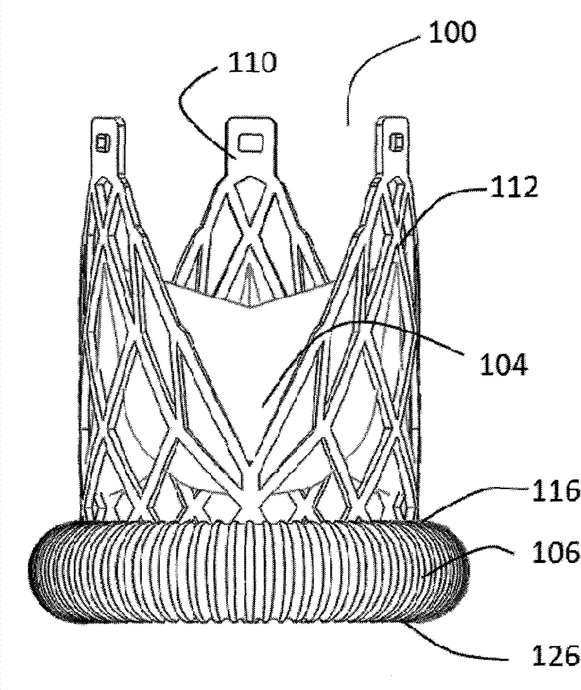
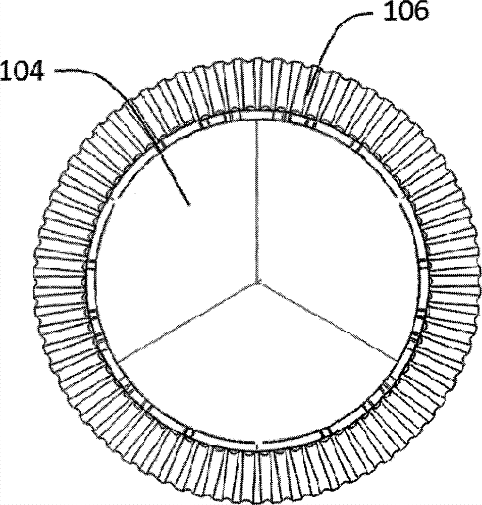
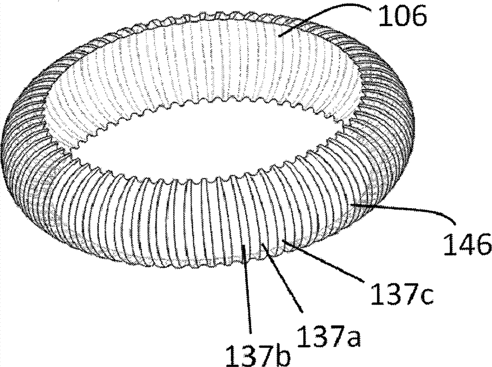
[0053] Such as Figure 1a with Figure 1b As shown, an aortic valve stent 100 for preventing paravalvular leakage includes a stent 110 and an artificial valve 104. The stent 110 is composed of a plurality of grid units 112, and the artificial valve 104 is connected to the grid unit. 112, a sealing unit 106 is provided at the bottom of the stent 110. The sealing unit 106 is made of a metal memory material and covered with a film. In a natural state, the sealing unit 106 runs along the axial direction of the stent. It is arched outside and has a ring structure along the circumference of the bracket. One end of the sealing unit 106 is free and is a free end 116. The other end of the sealing unit 106 is fixed to the bottom of the bracket 110 by a fixing member. The fixed end 126, when the sealing unit 106 is compressed into the sheath, the free end 116 of the sealing unit 106 is turned around the fixed end 126 to the bottom end of the bracket, so that the sealing unit 106 is not It ...

specific Embodiment 2

[0056] Such as Figure 6a with Figure 6b As shown, an aortic valve stent 100 for preventing paravalvular leakage includes a stent 110 and an artificial valve 104. The stent 110 is composed of a plurality of grid units 112, and the artificial valve 104 is connected to the grid unit. 112, a sealing unit 206 is provided at the bottom of the bracket 110. The sealing unit 206 is made of a metal memory material and covered with a film. In a natural state, the sealing unit 206 runs along the axial direction of the bracket. It is arched outside and has a ring structure along the circumference of the bracket. One end of the sealing unit 206 is free and is a free end 216. The other end of the sealing unit 206 is fixed to the bottom of the bracket 110 by a fixing member. The fixed end 226, when the sealing unit 206 is compressed into the sheath, the free end 216 of the sealing unit 206 is turned around the fixed end 226 toward the bottom end of the bracket, so that the sealing unit 206 do...

specific Embodiment 3

[0062] Such as Figure 11a with Figure 11b As shown, an aortic valve stent 100 for preventing paravalvular leakage includes a stent 110 and an artificial valve 104. The stent 110 is composed of a plurality of grid units 112, and the artificial valve 104 is connected to the grid unit. 112, a sealing unit 306 is provided at the bottom of the bracket 110. The sealing unit 306 is made of a metal memory material and covered with a film. In a natural state, the sealing unit 306 runs along the axial direction of the bracket. It is arched outside and has a ring structure along the circumference of the bracket. One end of the sealing unit 306 is free and is a free end 316. The other end of the sealing unit 306 is fixed to the bottom of the bracket 110 by a fixing member. The fixed end 326, when the sealing unit 306 is compressed into the sheath, the free end 316 of the sealing unit 306 is turned around the fixed end 326 to the bottom end of the bracket, so that the sealing unit 306 is n...


PUM


Abstract

The invention discloses an aortic valve stent (100) capable of preventing perivalvular leakage. The aortic valve stent (100) capable of preventing perivalvular leakage comprises a stent (110) and an artificial valve (104), wherein the stent (110) is composed of a plurality of grid cells (112); the artificial valve (104) is connected to the grid cells (112); a sealing unit (106) is arranged at the bottom of the stent (110); the sealing unit (106) is made from a metal memory material and laminated; in a natural state, the sealing unit (106) is arched outwards along the axial direction of the stent and of an annular structure along the peripheral direction of the stent (110); one end of the sealing unit (106) is free and is a free end (116); the other end of the sealing unit (106) is fixed with the bottom of the stent (110) by a fixing element, and is a fixed end (126); when the sealing unit (106) is compressed to enter a sheathing canal, the free end (116) of the sealing unit (106) turns towards the bottom end of the stent and around the fixed end (126), thus the sealing unit (106) is not superposed with the stent (110).

Description

Technical field: [0001] The invention belongs to the field of medical devices, and specifically relates to an aortic valve stent for preventing paravalvular leakage. Background technique: [0002] Aortic valve stenosis is a common heart valve disease in the elderly. The incidence rate is about 4% for patients aged 75-85, and it increases to about 7% for patients over 85 years old. Among them, the incidence of aortic valve stenosis due to aortic valve calcification is 2%-7%, and its proportion increases with age. It has become an important cause of heart failure, arrhythmia, syncope and sudden death in the elderly one. Surgical valve replacement is the first traditional treatment method. However, the mortality rate is very high for patients with advanced age, low heart function, or multiple complications. In addition, conservative medical treatment and balloon dilatation are both poorly cured and complicated. Symptoms and recurrence rate are high. [0003] Since 2002, Cribier et ...

Claims


Application Information

Patent Timeline
Patent Type & Authority Applications(China)
IPC IPC(8): A61F2/24
CPCA61F2/2409A61F2/2418A61F2220/0075A61F2250/0069
Inventor 李毅斌吕世文徐志云李佳楠
Owner NINGBO JENSCARE BIOTECHNOLOGY CO LTD
Why Eureka
Try Eureka