
Badminton racket and manufacturing method thereof

A badminton racket and racket technology, which is applied in the field of sports equipment, can solve the problems of large swing wind resistance, increased force-bearing area, and small direct force-bearing area, etc., and achieves improved hitting stability, reduced vibration, and improved racket hitting feeling. clear effect

Active Publication Date: 2014-04-09
SUQIAN ADK COMPOSITES +1
View PDF7 Cites 14 Cited by
  • Summary
  • Abstract
  • Description
  • Claims
  • Application Information

AI Technical Summary

Problems solved by technology

[0003] Existing composite carbon fiber badminton rackets that adopt air pressure molding, the inner cavity of the racket frame needs to be pre-installed with nylon air ducts, and the joint between the racket frame and the racket shaft (the tee part) needs to wear nylon air ducts, and the compressed air flows from the racket shaft. The other end enters the nylon air duct to make the racket frame internally press-shaped. In order to prevent the joint between the racket rod and the racket frame from detaching, more pieces of preformed patches will be used at the joint between the racket frame and the racket shaft (tee part). The package is reinforced, so the tee part of the badminton racket cannot be made smaller, and the wind resistance of the swing when playing is relatively large
Due to the wind pressure in the nylon air duct, the tight joint area formed by the racket shaft and the racket frame is small. When the power of the racket shaft is transmitted to the racket frame when playing ball, the conduction area is too small, resulting in the gap between the racket shaft and the racket frame at the three-way part. The force per unit area is relatively large, resulting in a large internal stress at the joint, which may cause the joint to break when the ball is hit hard
[0004] There is also a composite carbon fiber badminton racket with a "T" joint structure. The tee part is a "T" joint that combines the racket rod and the racket frame with resin. It can only be combined with the outer frame surface of the racket frame. When the racket frame is press-molded, there will be a gap between the shaft or racket frame and the joint surface of the "T" joint. At this time, the force of the racket shaft passes through the "T" joint When it is transmitted to the racket frame, it will not be supported, so that the transmission force of the racket shaft will directly act on the joint between the racket shaft and the racket frame, because the direct joint between the racket shaft and the racket frame (the tee part) is only joined by the preformed patch , so the direct force-bearing area is small, which will lead to an increase in the unit force-bearing area, resulting in a large internal stress at the joint, which may lead to breakage at the direct joint between the racket frame and the racket shaft when hitting the ball vigorously
For the strength of the direct junction between the racket shaft and the racket frame, the direct junction between the racket frame and the racket shaft must be reinforced with more pieces of preformed patches, so the tee part of the badminton racket cannot be made smaller, and the racket is swung when playing. greater wind resistance

Method used


Image

  • Badminton racket and manufacturing method thereof
  • Badminton racket and manufacturing method thereof
  • Badminton racket and manufacturing method thereof

Examples


Embodiment

[0123] A method for manufacturing badminton rackets, which takes the following steps to achieve

[0124] 1. The method of coating foamed resin 1-2a on lightweight non-woven shock-absorbing fiber cloth 1-1 is as follows:

[0125] (1) Blending foam resin

[0126] The main components of the foamed resin are: bisphenol A epoxy resin, natural rubber, PU foam powder, and methyl ethyl ketone solvent. The weight ratio is:

[0127] Bisphenol A epoxy resin 4~9

[0128] Natural rubber 12~18

[0129] PU foaming powder 38~50

[0130] Methyl ethyl ketone solvent 28~35

[0131] The above-mentioned materials are all commercially available materials.

[0132] (2) Use a fully automatic coating machine to uniformly coat the formulated foamed resin on one side of the lightweight non-woven shock-absorbing fiber cloth according to the thickness of 0.20-3mm, and dry it to make a foamed resin coated cloth for use.

[0133] The thickness of the lightweight non-woven shock-absorbing fiber cloth is less than 3mm.

[01...


PUM

PropertyMeasurementUnit
depthaaaaaaaaaa
widthaaaaaaaaaa
heightaaaaaaaaaa

Abstract

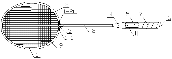
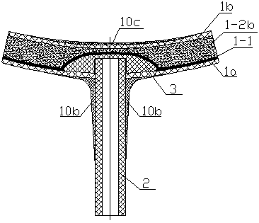
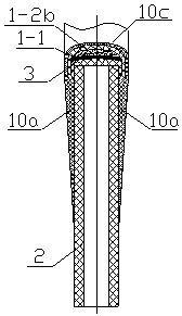
The invention relates to physical exercise equipment, in particular to a badminton racket and a manufacturing method thereof. The badminton racket comprises a racket frame, racket strings, string protecting nails, a racket rod, an end cap, a front sleeve, a racket handle, handle leather and a rear sleeve. The end cap is mounted in the tee joint position where the racket frame and the racket rod are connected, the racket frame, the front end of the racket rod and the end cap are connected together tightly, the front sleeve and the racket handle are mounted at the rear end of the racket rod, the handle leather is wound on the racket handle, the rear sleeve is mounted on the rear portion of the racket handle, and the racket strings are arranged on the racket frame through the string protecting nails in a penetrating mode. An end cap upper end face, an end cap side face and an end cap lower end face are provided, a blind hole is formed in the middle of the end cap lower end face of the end cap, and the racket rod stretches in the racket frame through the joint of the outer surface of the upper end of the racket rod and the inner surface of the blind hole of the end cap. Light non-woven shock-absorption fiber cloth is arranged in the racket frame, one side of the light non-woven shock-absorption fiber cloth is coated with a foam resin layer, the foam resin layer fills the inner cavity of the racket frame after swelled, and the light non-woven shock-absorption fiber cloth is fit with the inner surface of the outer frame of the racket frame.

Description

Technical field [0001] The invention relates to a sports equipment, in particular to a badminton racket and a manufacturing method thereof. Background technique [0002] Badminton is a wide-ranging sport. For users, it is very important to use a good badminton racket during sports. If a bad racket is used, it will affect the user’s feeling and mood. The impact is huge, and even sports injuries. What kind of racket is considered a good racket? A racket with fast speed, high stability, good power transmission performance and low vibration is a good racket. The industry has been committed to designing and manufacturing a good badminton racket to meet the needs of users and badminton sports. [0003] In the existing composite carbon fiber badminton rackets that are formed by wind pressure, the inner cavity of the racket frame needs to be pre-installed with a nylon air duct. The joint between the racket frame and the shaft end (the three-way part) requires a nylon air tube, and the co...

Claims


Application Information

Patent Timeline
Patent Type & Authority Applications(China)
IPC IPC(8): A63B49/00D06M15/564D06M15/693D06M15/55C08L77/00C08L63/00C08K7/00C08K7/06A63B49/032A63B49/08A63B102/04
Inventor 蔡人辉刘春明
Owner SUQIAN ADK COMPOSITES
Learn More