Engine vapor recycle and photolysis duplex combustion energy conservation and emission reduction method and device

An energy-saving emission reduction, engine technology, applied in the direction of engine components, combustion engines, machines/engines, etc., can solve the problems of insufficient combustion of fuel or gas, polluted air, environmental pollution, etc., to improve the effect of energy saving and emission reduction, reduce emissions Visible, noise-reducing effect

Inactive Publication Date: 2014-04-09
俞志毅
View PDF8 Cites 1 Cited by
  • Summary
  • Abstract
  • Description
  • Claims
  • Application Information

AI Technical Summary

Problems solved by technology

[0004] The principle of the existing engine (internal combustion engine) exhaust system is: install an exhaust pipe on the engine, connect it with the exhaust branch pipe, and install a muffler at the end of the exhaust branch pipe; when the engine is working, gas or fuel oil enters the engine combustion chamber to explode The exhaust gas generated in the end is dissipated through the exhaust pipe, the exhaust branch pipe and the muffler's own heat absorption function, and the waste heat and exhaust gas are discharged from the outlet of the muffler, causing relatively loud noise, and the incompletely burned exhaust gas contains a large amount of toxic and harmful substances. Substances can seriously pollute the air, especially when the car is parked and idling, the fuel or gas is severely incompletely burned, resulting in more serious energy waste and environmental pollution
[0005] At present, gas or fuel oil enters the combustion chamber of the engine for explosive combustion, during which a light source will be generated, which can photolyze part of the water vapor, and the photolysis of water vapor will produce combustible gas, which will directly enter the exhaust gas discharge system and be discharged into the atmosphere, which will cause energy waste of

Method used


Image

  • Engine vapor recycle and photolysis duplex combustion energy conservation and emission reduction method and device

Examples


Embodiment Construction

[0021] The specific embodiments of the present invention will be described in detail below with reference to the accompanying drawings.

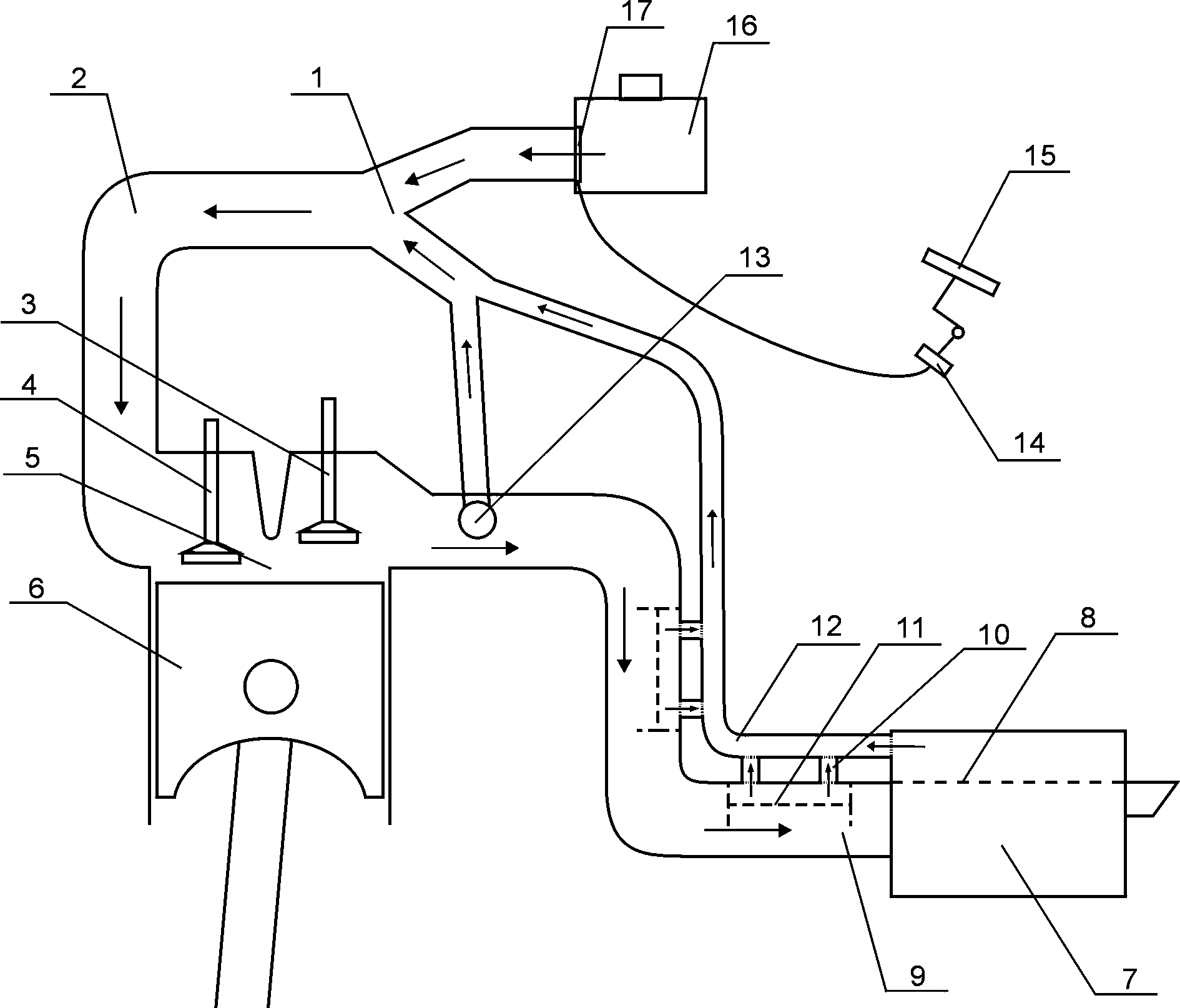
[0022] like figure 1 As shown, the present invention includes an engine piston 6, a combustion chamber 5, an intake valve 4 and an exhaust valve 3, one end of the intake pipe 2 is connected with the trident pipe 1, one end of the trident pipe 1 is connected with the air filter 16, and the other end is connected with the suction pipe 1. The heat pipes 12 are connected; the heat absorption pipes 12 are provided with a plurality of heat absorption ports 10 and the heat absorption pipes 11 installed on the exhaust branch pipes 9 of the outer asbestos and asbestos cloth are connected, and the ends are connected with the muffler 7; The exhaust gas, especially the water vapor, enters the suction pipe 12; the control valve 17 on the air filter 16 is connected with the contact switch 14 on the accelerator pedal 15 with a wire; When the engine is at ...


PUM


Abstract

The invention relates to an engine vapor recycle and photolysis duplex combustion energy conservation and emission reduction method and device, and belongs to the field of engine energy conservation and environment protection. An existing engine exhaust system has the defects that energy consumption and emission are high, pollution to the environment is serious, and engine noise is large. According to the engine vapor recycle and photolysis duplex combustion energy conservation and emission reduction method and device, a heat absorber is arranged in an exhaust branch pipe, a Y-pipe is arranged on an air inlet pipe of an engine, and one port of the Y-pipe is connected with the heat absorber. When the engine exhausts air, vapor in tail gas is heated again by using the heat absorbing function of the heat absorber, the exhaust gas is driven to pass through the engine, enter a combustion chamber and be combusted again in a photolysis mode together, the vapor and the heat energy can be utilized in a duplex mode, and thus energy consumption of the engine is reduced effectively. Meanwhile, tail gas emission is reduced greatly, the emission of the engine can reach the national standard VI and the national standard VII, emission reduction reaches more than 80% when the engine is in an idle mode, and the effects of energy conservation, consumption reduction and emission reduction are truly achieved.

Description

technical field [0001] The invention belongs to the field of engine energy saving and emission reduction, and in particular relates to a method and device for energy saving and emission reduction of engine water vapor photolysis complex combustion. Background technique [0002] Water energy is an inexhaustible resource in nature that can be continuously regenerated, continuously utilized, and inexhaustible. In 2008, scientists around the world successfully researched in Iceland and found that water can be decomposed by light to produce hydrogen, and oxygen can be burned to generate water. It is a harmless and very clean energy source. With the continuous advancement of science and technology, the mystery of photolysis of water has been continuously uncovered. [0003] At present, the energy utilization rate of the engine (internal combustion engine) is only 20%. [0004] The principle of the existing engine (internal combustion engine) exhaust system is: install an exhau...

Claims


Application Information

Patent Timeline
Patent Type & Authority Applications(China)
IPC IPC(8): F02M25/07F02M25/10F02M26/13
CPCY02T10/121Y02T10/12
Inventor 俞志毅俞学成
Owner 俞志毅
Why Eureka
Try Eureka