Hydro-pneumatic spring device with inerter and damper connected in parallel

A technology for oil-gas springs and inertial containers, applied in springs, springs/shock absorbers, shock absorbers, etc., can solve the problems of backlash bearing capacity, difficult processing and high cost of mechanical inertial containers, and improve driving comfort and performance. Handling stability, ease of manufacture and application, effect of damping high frequency vibration

Inactive Publication Date: 2014-04-09
JIANGSU UNIV
View PDF7 Cites 5 Cited by
  • Summary
  • Abstract
  • Description
  • Claims
  • Application Information

AI Technical Summary

Problems solved by technology

[0007] Chinese patent 201210426429.8 discloses an integrated oil-gas spring device, which is a ball screw-type inerter working chamber coaxially arranged in the oil-gas spring damping cylinder, realizing the parallel structure of the inerter, damper, and gas spring. Although the device can effectively buffer and attenuate the impact and vibration from the low-frequency band of the road surface, it cannot buffer and attenuate the impact and vibration from the high-frequency band of the road surface, and the ball screw type inerter has high cost and is not easy to process, so friction must be considered Non-linear factors and other issues
Chinese patent 200810123830.8 discloses a hydraulic inerter device, which consists of a hydraulic cylinder, a high-pressure hose and a mass block. In vehicle applications, it needs to be connected in parallel with a damping device to prevent the inerter from being broken down. At the same time, the working space is large , the arrangement is not flexible
[0008] Therefore, there is an urgent need in engineering for a suspension device with simple structure, flexible layout, integrated inertial container and oil-pneumatic spring, which can buffer and attenuate the impact and vibration caused by uneven road surface in the whole frequency range, and at the same time solve the problem of Problems with limited backlash and carrying capacity of mechanical inerters

Method used


Image

  • Hydro-pneumatic spring device with inerter and damper connected in parallel
  • Hydro-pneumatic spring device with inerter and damper connected in parallel
  • Hydro-pneumatic spring device with inerter and damper connected in parallel

Examples


Embodiment Construction

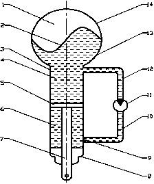
[0019] figure 1 Shown is an oil-pneumatic spring device in which an inerter and a damper are connected in parallel, including a gas spring working part, an inerter working part, a damping working part and an outer protection part. The working part of the gas spring includes an air chamber 1, an upper hemispherical chamber 14, a lower hemispherical chamber 13, and a rubber oil-gas diaphragm 2. The rubber oil-gas diaphragm 2 divides the gas chamber 1 into an upper hemispherical chamber 14 and a lower hemispherical chamber 13, and the upper hemispherical chamber 14 is filled with The elastic medium is nitrogen, and the lower hemispherical chamber 13 is filled with force transmission medium oil. The air chamber 1 is fixed on the upper end of the hydraulic cylinder 3; the working part of the inerter includes a hydraulic motor 11, a high-pressure hose A12 and a high-pressure hose B10. The hose A12 and the high-pressure hose B10 are connected to the small holes on the upper and lowe...


PUM


Abstract

The invention discloses a hydro-pneumatic spring device with an inerter and a damper connected in parallel. The hydro-pneumatic spring device comprises a single air chamber hydro-pneumatic spring and a hydraulic motor. In the hydro-pneumatic spring device, a hydraulic cylinder and a gas spring are connected in series and of an integral structure and can buffer and attenuate high-band impact and vibration from a road surface. When external force from a vehicle body and the ground is exerted on a piston rod inside a working cylinder in the axial direction of a shock absorber, a piston does linear movement relative to a cylinder body, the pressure difference is formed between an upper cavity of the hydraulic cylinder and a lower cavity of the hydraulic cylinder, working oil passes through a damper valve, the hydraulic motor and the gas spring, the inerter function is achieved, and the effect that the inerter and the damper are connected in parallel and then connected with the gas spring in series is achieved through combination with the electromechanical analog theory. The hydro-pneumatic spring device can buffer and attenuate impact and vibration from the rough road surface within the full-frequency-domain range, is compact in structure and flexible to arrange, and has certain engineering application value.

Description

technical field [0001] The invention relates to an oil-gas spring device, in particular to an oil-gas spring device in which an inerter and a damper are connected in parallel and then connected in series with a gas spring. Background technique [0002] In recent years, mechatronics has become an important direction of technological development. Now the main use is based on the similarity between force and current, speed and voltage, and establishes the electromechanical simulation theory that the mass, damping and spring components of the mechanical system correspond to the capacitance, resistance and inductance components of the circuit system respectively. Since the mass element of the mechanical system actually corresponds to a capacitor grounded at one end, the incomplete equivalence between the mechanical network and the circuit network results. Therefore, the application of electromechanical simulation theory is greatly restricted. [0003] In response to this phenom...

Claims


Application Information

Patent Timeline
IPC IPC(8): F16F9/088F16F9/096F16F9/32
Inventor 陈龙蒋涛张孝良汪若尘沈钰杰
Owner JIANGSU UNIV
Why Eureka
Try Eureka