Device for controlling internal combustion engine

A technology of a control device and an internal combustion engine, applied in engine control, internal combustion piston engine, electrical control, etc., can solve the problem of inability to output PM accumulation, and achieve the effect of inhibiting accumulation

Inactive Publication Date: 2014-04-09
TOYOTA JIDOSHA KK
View PDF4 Cites 10 Cited by
  • Summary
  • Abstract
  • Description
  • Claims
  • Application Information

AI Technical Summary

Problems solved by technology

[0004] However, when the amount of PM accumulation between the electrodes exceeds a fixed amount, the resistance value between

Method used


Image

  • Device for controlling internal combustion engine
  • Device for controlling internal combustion engine
  • Device for controlling internal combustion engine

Examples


Embodiment approach 1

[0036] [About the structure of the system of this embodiment]

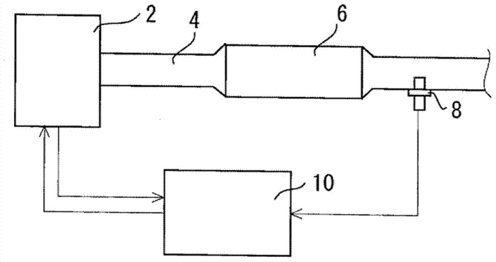
[0037] figure 1 It is a figure for explaining the overall structure of the system which concerns on this embodiment of this invention. exist figure 1 In the system shown, a DPF (Diesel Particulate filter) 6 is provided on the exhaust path 4 of the internal combustion engine 2 . The DPF6 is a filter that collects particulate matter (PM: particulate matter) contained in exhaust gas. Downstream of the DPF 6 in the exhaust path 4, a PM sensor 8 (particulate sensor) is provided. The PM sensor 8 is used to detect the amount of PM in the exhaust gas passing through the DPF 6 .

[0038] This system includes a control device 10 . Various sensors other than the PM sensor 8 are connected to the input side of the control device 10 . Furthermore, various actuators of the internal combustion engine 2 are connected to the output side of the control device 10 . The control device 10 executes predetermined programs based on...

Embodiment approach 2

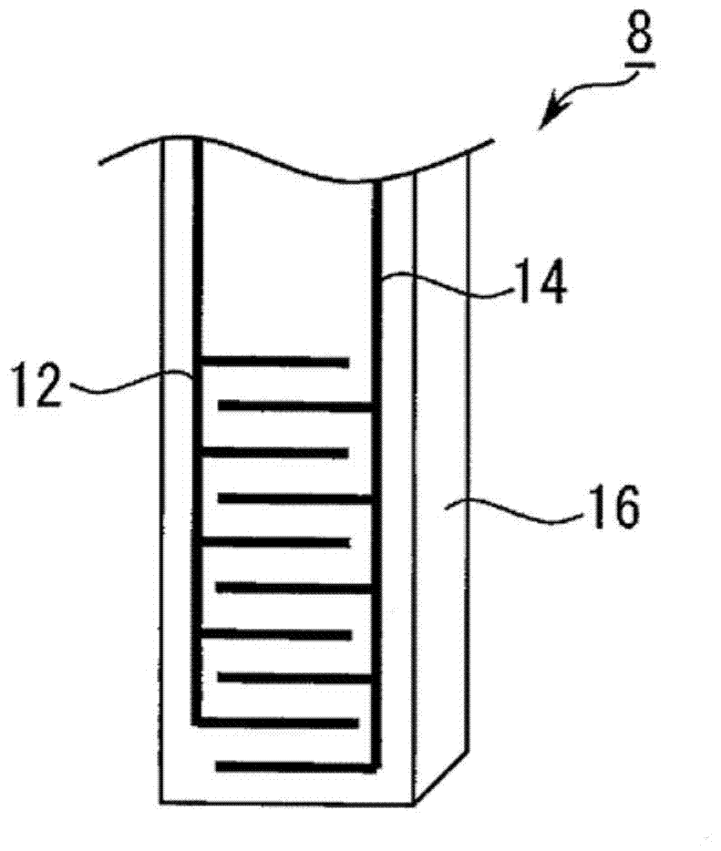
[0081] The system and the PM sensor of Embodiment 2 have the same figure 1 , figure 2 The system shown has the same structure as the PM sensor. In the system of Embodiment 2, instead of the control to form the poisoning prevention layer between the electrodes 12 and 14 after the failure detection of the DPF 6 , the poisoning prevention layer is formed by predicting the timing when the amount of PM emission increases. .

[0082] As described above, during the regeneration of the DPF 6 , for example, by increasing the temperature of the exhaust gas, the PM deposited on the DPF 6 is combusted and removed. Therefore, it can be expected that the amount of PM and poisons flowing out downstream of the DPF 6 will increase during the period in which this treatment is performed. Therefore, it is preferable to suppress the adhesion of PM and the like between the electrodes 12 and 14 during this period.

[0083] Therefore, in the system according to the second embodiment, before the ...

Embodiment approach 3

[0104] The system and PM sensor of Embodiment 3 have the same figure 1 , 2 The system shown has the same structure as the PM sensor. In Embodiment 3, control in which the controls of Embodiments 1 and 2 are combined is executed.

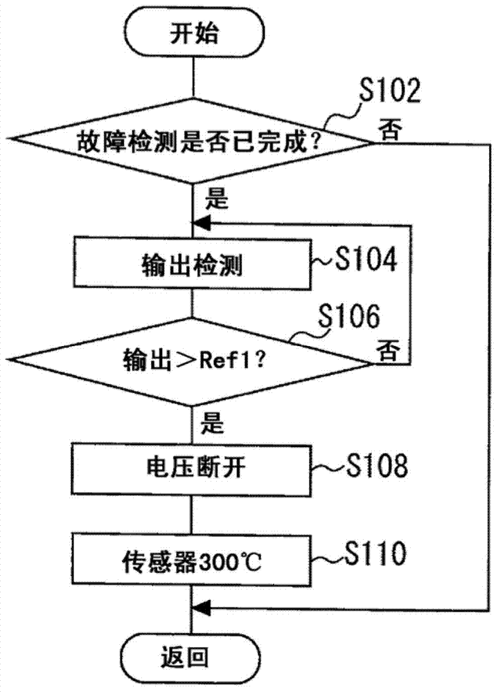
[0105] Image 6 It is a flowchart for explaining the control executed by the control device 10 in Embodiment 3 of the present invention. exist Image 6 The program, first, executes the same as that of Embodiment 2 Figure 5 The same processing as in S202 to S214. That is, it is judged whether the regeneration of the DPF 6 is predicted ( S202 , 204 ), and when the regeneration of the DPF 6 is predicted, PM removal is prohibited ( S206 ). Thereafter, until the regeneration of the DPF is completed (S208), and until a certain amount of PM is considered to have accumulated on the DPF 6, the prohibition of PM removal is continued (S210, 212), and when the accumulation of PM is confirmed, PM removal is permitted. (S214). After that, the processing t...


PUM


Abstract

In the present invention, a microparticle sensor (8) is installed in an exhaust path (4) of an internal combustion engine (2). A device (10) for controlling the internal combustion engine (2) detects the microparticle content of the exhaust gas in the exhaust path (4) according to the output of the microparticle sensor (8). In a first period, the device (10) for controlling the internal combustion engine (2) impresses a collection voltage for collecting microparticles between electrodes of the microparticle sensor, and forms a microparticulate layer on the surface of the electrodes. The state in which the particulate layer is formed is maintained during a second period. "The state in which the particulate layer is formed is maintained" connotes maintaining the state in which the particulate layer is formed as well as prohibiting a control for removing the particulate layer.

Description

technical field [0001] This invention relates to a control device for an internal combustion engine, and more specifically, to a control device for an internal combustion engine provided on an exhaust path of the internal combustion engine and having a particle sensor for detecting the amount of particles in the exhaust gas. Background technique [0002] For example, in the system of Patent Document 1, a DPF (Diesel Particulate Filter: Diesel Particulate Filter) that traps particulate matter (particulate matter; hereinafter also referred to as "PM") in the exhaust gas is disposed on the exhaust path of the internal combustion engine. ), and downstream of the DPF, a PM sensor for detecting the amount of PM passing through the DPF without being captured by the DPF is arranged. [0003] The PM sensor of Patent Document 1 includes an insulating layer to which PM adheres, and electrodes arranged on the insulating layer at intervals from each other. This PM sensor is in contact w...

Claims


Application Information

Patent Timeline
IPC IPC(8): F01N3/00F01N3/02G01N27/02
CPCF01N11/00Y02T10/40G01N15/0606F01N2560/20F02D41/06F02D41/1494F02D41/18G01N2015/0046F01N9/002F01N2550/04G01N15/0656F02D41/22F02D41/1467F02D41/029Y02T10/47F01N2560/05F02D41/1466F02D41/0047
Inventor 西嶋大贵桥田达弘
Owner TOYOTA JIDOSHA KK
Why Eureka
Try Eureka