Desulfurization device and desulfurization method for promoting removal of PM2.5 in clean flue gas after wet desulphurization

A desulfurization device, wet desulfurization technology, applied in the direction of combined devices, separation methods, chemical instruments and methods, etc., can solve the problems of high steam consumption, high energy consumption, large resistance, etc., to improve the washing and trapping effect, trap Improve collection efficiency and reduce energy consumption

Active Publication Date: 2014-04-16
SOUTHEAST UNIV
View PDF6 Cites 20 Cited by
  • Summary
  • Abstract
  • Description
  • Claims
  • Application Information

AI Technical Summary

Problems solved by technology

[0003] The use of dust removal facilities such as electric bags, cloth bags, and new electric dust collectors can only reduce the PM entering the wet desulfurization tower 2.5 Concentration, for PM formed during WFGD 2.5 Powerless; installing wet electrostatic precipitator downstream of WFGD system can effectively remove PM in desulfurized flue gas 2.5 , but due to high investment and operating costs, it is still difficult to enter a comprehensive practical stage
In addition, in view of the fact that flue gas is in a saturated state after wet desulfurization, the water vapor phase change technology based on the condensation characteristics of supersaturated water vapor on the surface of particles is the best way to promote the wet desulfurization of PM in flue gas. 2.5 An important measure for removal. To adopt this technology, the net flue gas of wet desulfurization must first be supersaturated. The simplest measure is to add steam or set up a heat exchanger to cool the flue gas, but the latter will cause the supersaturated water vapor to be mainly Condensation on the wall of the heat exchanger, weakening PM 2.5 Coagulation growth effect, and high energy consumption
The supersaturation established by adding steam will decrease sharply with the increase of the desulfurization net flue gas temperature, so that the steam consumption is too high when it is applied to the occasion with high desulfurization net flue gas temperature (≥55~70℃).
The invention patent with the application number of 200710132250.0 discloses a method of adding steam to desulfurized clean flue gas to establish PM 2.5 The supersaturated water vapor environment required for condensation and growth, and then the method of removing the condensed and grown dust droplets by the wire mesh eliminator; but the supersaturation is achieved by adding steam alone, and the energy consumption is too high, especially when the desulfurization net When the flue gas temperature is high
At the same time, given that PM 2.5 After condensing and growing up, it becomes dust-containing mist droplets covered with a layer of liquid film on the outer surface. It needs to be matched with dust removal equipment that can remove mist droplets, such as wet dust collectors and mist eliminators. The final dust-laden mist has a better removal effect, but when it is applied to the limestone-gypsum desulfurization process, it is easy to block and has a large resistance; although the baffle plate demister is currently the most commonly used wet desulfurization demister , but it only has a better removal effect on droplets of tens of microns, while PM 2.5 Difficult to coagulate and grow to this particle size range

Method used


Image

  • Desulfurization device and desulfurization method for promoting removal of PM2.5 in clean flue gas after wet desulphurization
  • Desulfurization device and desulfurization method for promoting removal of PM2.5 in clean flue gas after wet desulphurization
  • Desulfurization device and desulfurization method for promoting removal of PM2.5 in clean flue gas after wet desulphurization

Examples


Embodiment 1

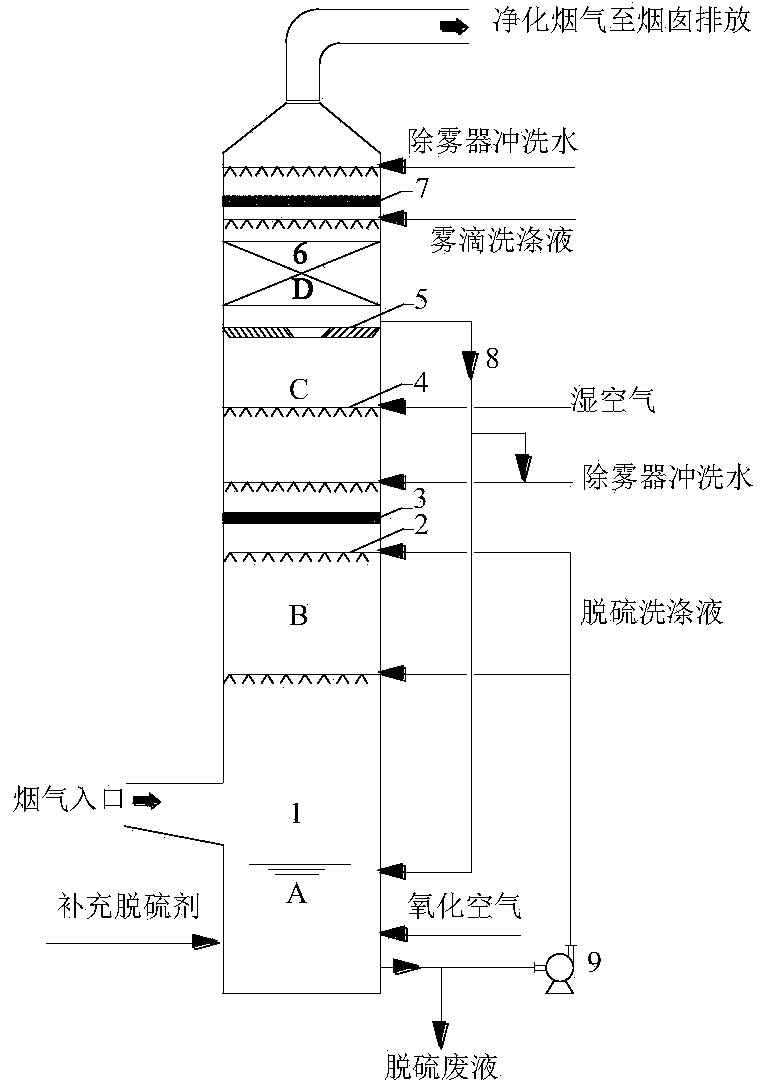
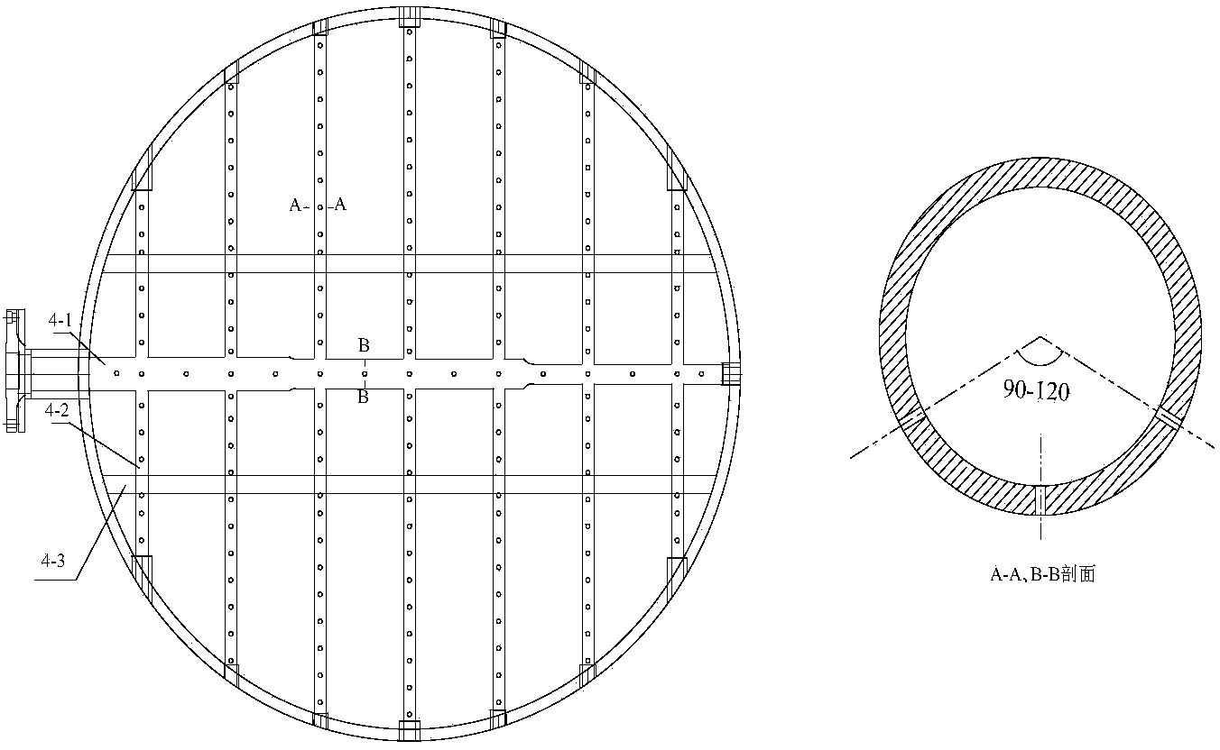
[0035] A desulfurization device, applied to the PM in the promoted wet desulfurization net flue gas 2.5 In the removal method, the desulfurization tower 1 of the desulfurization device is an absorption tower with multi-stage functional sections, the bottom of the tower is the desulfurization liquid oxidation zone A, the middle part is the desulfurization washing zone B, and the top is PM 2.5 The water vapor phase change region C where condensation and growth occurs and the droplet trapping device D that traps the dusty mist after condensation grows. In the desulfurization liquid oxidation zone A, there are oxidation air inlet, supplementary desulfurizer inlet and desulfurization washing liquid outlet. The flue gas inlet is provided at the lower part of the desulfurization washing area B, and the desulfurization washing liquid inlet is provided at the top, which can adopt empty tower spray, tray or packing structure. A wet air distributor 4 is provided in the middle of the wat...

Embodiment 2

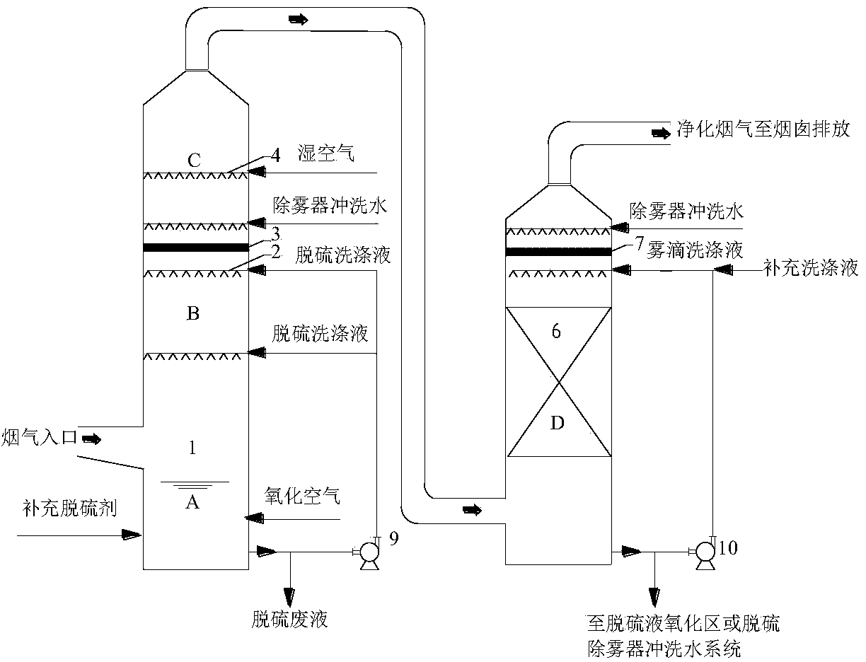
[0038] Such as figure 2 As shown, the difference from Example 1 is that the droplet trapping device D and the flue gas desulfurization washing device are split, the flue gas desulfurization washing device is a desulfurization tower 1, and the desulfurization tower 1 only includes the desulfurization liquid oxidation zone A, desulfurization Washing area B and water vapor phase change area C; the mist trapping device can be a structure such as a spray scrubber, a packed scrubber, a Venturi scrubber, etc., and the washing liquid and the demister flushing water after trapping the dust mist Part of it is recycled by the mist washing liquid circulation pump 10, and part of it is returned to the desulfurization liquid oxidation zone A or used as flushing water for the desulfurization eliminator 3. All the other are with embodiment 1.

Embodiment 3

[0040] The flue gas is produced by a fully automatic coal-fired boiler with a flue gas volume of 300Nm 3 / h, the desulfurization tower adopts a spray tower with a tower diameter of 200mm and a tower height of 4500mm, three-stage spraying, and a liquid-gas ratio of 18L / Nm 3 , The wet desulfurization technology is the limestone-gypsum method. The upper part of the desulfurization tower is equipped with a water vapor phase change area and a droplet collection device, and a baffle demister is installed between the water vapor phase change area and the desulfurization washing area; a washing liquid collector is installed between the water vapor phase change area and the droplet collection device. The liquid collector communicates with the desulfurization liquid oxidation zone through an overflow pipe, and a humid air distributor is installed in the middle of the water vapor phase change zone; two pieces of metal orifice corrugated structured packing are installed in the droplet tra...


PUM


Abstract

The invention discloses a desulphurization device and a desulphurization method for promoting removal of PM2.5 in clean flue gas after wet desulphurization. The desulphurization device comprises a flue gas desulphurization washing device and a fog drop collecting device which are connected in series, wherein the flue gas desulphurization washing device comprises a desulphurization liquid oxidation region, a desulphurization washing region and a water vapor phase change region which are arranged in sequence from bottom to top; the fog drop collecting device forms an integral or split structure together with the flue gas desulphurization washing device and is arranged on the flue gas desulphurization washing device or at an outlet. According to the method, flue gas enters the water vapor phase change region after SO2 is removed through the desulphurization washing region; wet air is filled through a wet air distributor, so that the clean flue gas after the wet desulphurization reaches an oversaturated state; oversaturated water vapor is nucleated and condensed on the PM2.5 surface, so that the PM2.5 is turned into dust fog drops with liquid films on the surfaces and the particle sizes are increased; the condensed expanded dust fog drops enter the fog drop collecting device and are collected through fog drop washing liquid and a defroster of the fog drop collecting device. According to the desulphurization device, the energy consumption for building an oversaturated water vapor environment can be effectively reduced and the PM2.5 emission problem of a wet flue gas desulphurization system is solved.

Description

technical field [0001] The invention belongs to a kind of PM in flue gas 2.5 The technical field of emission control, especially a method of applying the principle of water vapor phase change to promote wet desulfurization of PM in flue gas 2.5 A desulfurization device for removal and a method thereof. Background technique [0002] Wet flue gas desulfurization (WFGD) has become the 2 More than 80% of large and medium-sized coal-fired power plants adopt wet flue gas desulfurization process, and the application of this process in coal-fired industrial boilers, sintering flue gas and other fields is also increasing day by day. In the WFGD process, due to the washing effect of the desulfurization slurry, although the coarse dust in the flue gas can be removed, due to the atomization entrainment of the desulfurization slurry, the crystallization of desulfurization products, and various gas-liquid, gas-liquid-solid desulfurization Physical and chemical processes such as reactio...

Claims


Application Information

Patent Timeline
Patent Type & Authority Applications(China)
IPC IPC(8): B01D53/78B01D53/50B01D50/00
Inventor 杨林军潘丹萍吴昊姜业正
Owner SOUTHEAST UNIV
Why Eureka
Try Eureka