
Spectrum measurement device based on electro-optical effect and spectrum measurement method thereof

An electro-optic effect and spectral measurement technology, applied in the field of spectral analysis, can solve the problems of narrow spectral measurement range, low resolution, vibration sensitivity, etc., and achieve the effects of simple and easy production, high resolution, and strong anti-vibration ability.

Inactive Publication Date: 2014-04-16
NANJING UNIV OF POSTS & TELECOMM
View PDF7 Cites 9 Cited by
  • Summary
  • Abstract
  • Description
  • Claims
  • Application Information

AI Technical Summary

Problems solved by technology

[0005] The technical problem to be solved by the present invention is to overcome the technical problems of high cost, difficult manufacture, sensitivity to vibration, low resolution and narrow spectral measurement range in the prior art, and provide a spectrometer based on the electro-optic effect and its Spectral measurement method

Method used


Image

  • Spectrum measurement device based on electro-optical effect and spectrum measurement method thereof
  • Spectrum measurement device based on electro-optical effect and spectrum measurement method thereof
  • Spectrum measurement device based on electro-optical effect and spectrum measurement method thereof

Examples


Embodiment Construction

[0027] The technical scheme of the present invention is described in detail below in conjunction with accompanying drawing:

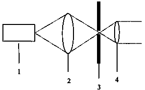
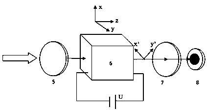
[0028] The idea of ​​the present invention is to use the electro-optic effect crystal under the same applied electric field, the phase difference between the two beams of birefringent light is also different after the linearly polarized light of different frequencies passes through the electro-optic effect crystal. Influenced by the light intensity, an electro-optic modulation component composed of two polarizers and an electro-optic effect crystal is constructed, and the optical power of the incident light to be measured after passing through the electro-optic modulation component under different applied electric fields is measured, and by solving the linear equations Obtain the spectrum of the incident light to be measured.

[0029] In order to optically shape the incident light, in this example, the incident light is first passed through an optical c...


PUM


Abstract

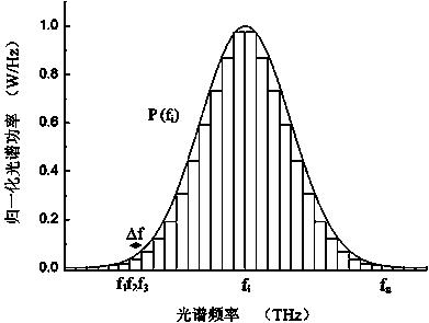
The invention discloses a spectrum measurement device based on the electro-optical effect. The spectrum measurement device based on the electro-optical effect comprises a first polarizing film, an electro-optical effect crystal, a second polarizing film and an optical detector all of which are sequentially arranged in the direction of incident light, wherein the polarizing direction of the first polarizing film is not parallel with the induction spindle direction of the electro-optical effect crystal under an external electric field. The invention further discloses a spectrum measurement method using the spectrum measurement device based on the electro-optical effect. The method comprises the steps that firstly, luminous power detected by the optical detector when different external impressed voltages are applied on the electro-optical effect crystal is measured, the obtained data of the luminous power serve as an augmented matrix, the augmented matrix is combined with a coefficient matrix formed by detectivity of the incident light of different frequencies from the spectrum measurement device under the different external impressed voltages, and then a linear system of equations is built; the linear system of equations is solved, the luminous power of each frequency component in the incident light to be detected is obtained, linear fitting and radiometric calibration are carried out on the luminous power, and the spectrum of the incident light to be detected is obtained. The spectrum measurement device based on the electro-optical effect and the spectrum measurement method have the advantages of being high in vibration resistance, high in resolution ratio, wide in spectrum measurement range and the like.

Description

technical field [0001] The invention relates to a spectrum measurement device, in particular to a spectrum measurement device based on electro-optic effect and a spectrum measurement method thereof, belonging to the technical field of spectrum analysis. Background technique [0002] A spectrometer is an important optical instrument. It is a basic device that combines optical methods with modern electronic data processing systems to accurately analyze the structure, composition and content of substances by obtaining spectral information of the substances under study. The spectrometer has the advantages of high analysis accuracy, large measurement range, and fast speed. It is widely used in metallurgy, geology, petrochemical, medical and health, and environmental protection. It is also an indispensable remote sensing instrument for military reconnaissance, space exploration, resource and hydrological detection, etc. Equipment (see literature [Li Quanchen, Jiang Yuejuan. Princ...

Claims


Application Information

Patent Timeline
Patent Type & Authority Applications(China)
IPC IPC(8): G01J3/447
Inventor 杨涛黄维许超周馨慧仪明东李兴鳌何浩培刘辉
Owner NANJING UNIV OF POSTS & TELECOMM
Learn More