Optical system for dressing display
An optical system and display technology, applied in the field of optical systems, can solve the problems of reducing the divided volume of the head-mounted display, and the optical device being unsuitable for patients to use.
- Summary
- Abstract
- Description
- Claims
- Application Information
AI Technical Summary
Problems solved by technology
Method used
Image

Examples
Embodiment 1
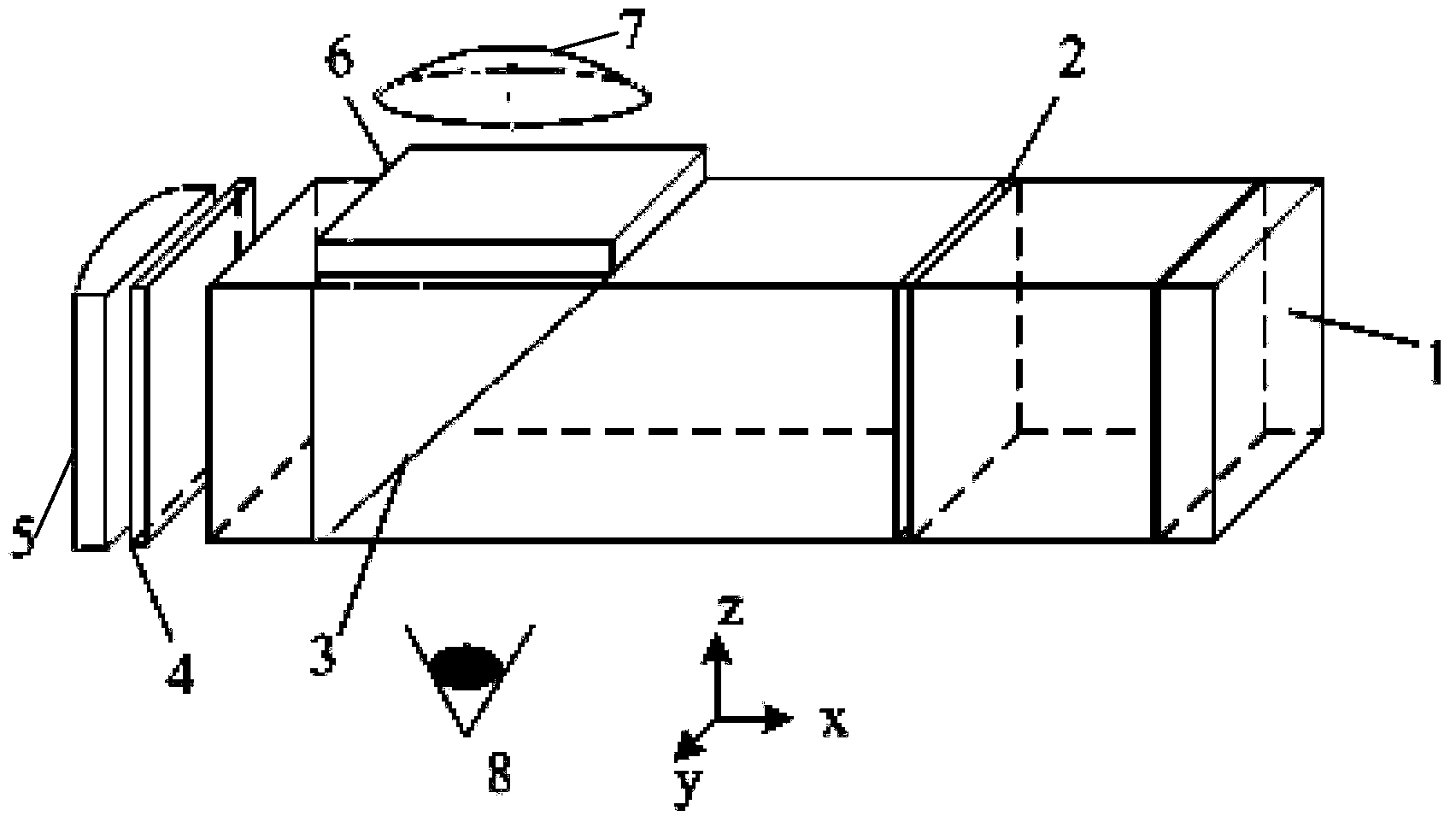
[0061] like figure 1 As shown, it is an optical system for wearable display, including: a display device 1 (OLED) that generates an image light signal; a 1 / 2 wave plate 2 arranged on the transmission optical path of the image light signal of the display device 1; The polarization beam splitter 3 at the output end of the / 2 wave plate 2; the first 1 / 4 wave plate 4 for receiving the image light signal (ie, the P component image light signal) passing through the polarization beam splitter 3; The image optical signal of the 1 / 4 wave plate 4 is reflected back through the reflector 5 of the first 1 / 4 wave plate 4 (embodiment 3); used to receive back through the first 1 / 4 wave plate 4 and then polarized The first lens 7 reflects the image light signal from the dichroic prism 3 . The beam-splitting surface of the polarization beamsplitter prism 3 reflects the image light signal passing through the first 1 / 4 wave plate 4 to a direction away from the human eye 8, and a second 1 / 4 wave ...
Embodiment 2
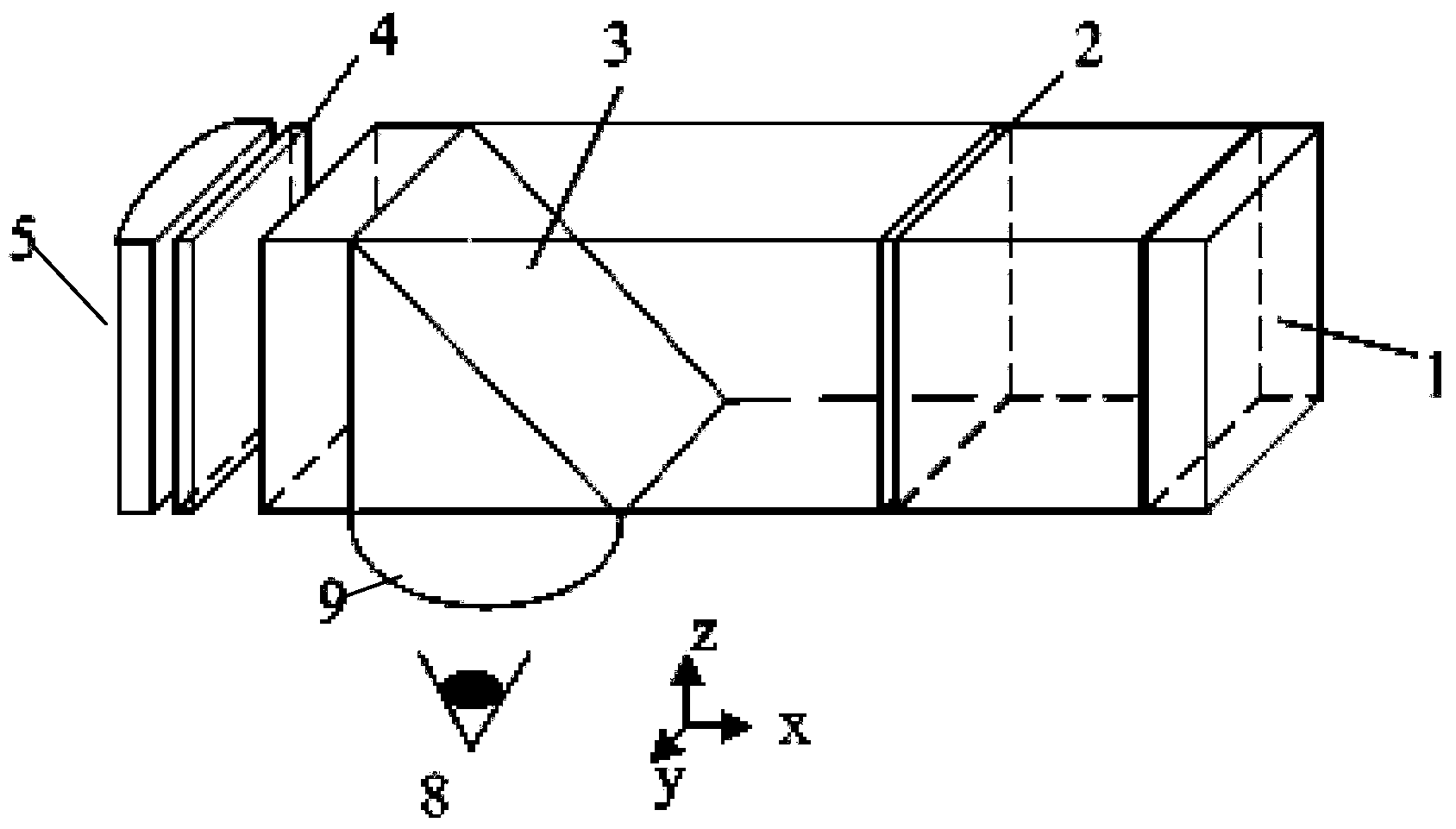
[0063] like figure 2 As shown, it is another optical system for wearable display, including: a display device 1 (OLED) that generates an image light signal; a 1 / 2 wave plate 2 set on the transmission optical path of the image light signal of the display device 1; The polarization beam splitter 3 at the output end of the 1 / 2 wave plate 2; the first 1 / 4 wave plate 4 for receiving the image light signal (ie, the P component image light signal) passing through the polarization beam splitter 3; The image light signal of a 1 / 4 wave plate 4 is reflected back through the reflector 5 of the first 1 / 4 wave plate 4 (embodiment 4 is used); for receiving it back through the first 1 / 4 wave plate 4 and then passing through the first 1 / 4 wave plate 4 The second lens 9 reflects the image light signal from the polarization splitter prism 3 . The beam-splitting surface of the polarizing beam-splitting prism 3 reflects the image light signal passing back through the first 1 / 4 wave plate 4 to th...
Embodiment 3
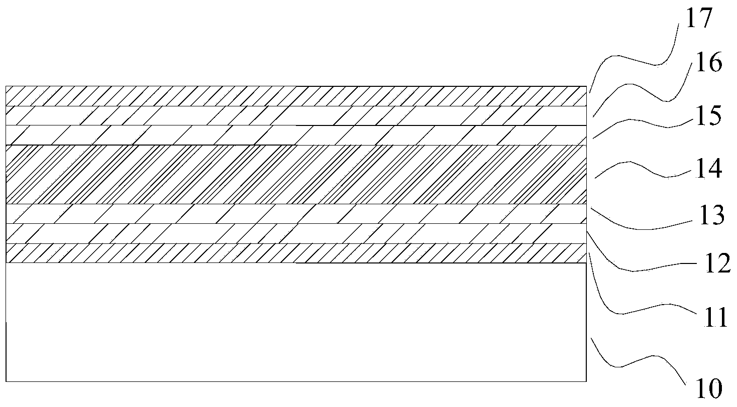
[0065] like image 3 As shown, it is a mirror, including a glass substrate 10 and a base layer, a high-reflection layer and a protective layer arranged on the glass substrate 10 in sequence, and a high-reflection film 19 is formed by the base layer, a high-reflection layer and a protective layer; the base layer and the glass The substrate 10 is closely attached, and the base layer includes Ti 3 o 5 Layer 11, SiO 2 Layer 12 and Al 2 o 3 Layer 13, where Ti 3 o 5 The layer 11 is closely attached to the glass substrate 10; the high-reflection layer includes a silver-copper alloy layer 14, and the silver-copper alloy layer 14 is formed by mixing 30% by weight copper and 70% by weight silver; the protective layer includes sequentially Al set 2 o 3 Layer 15, SiO 2 Layer 16 and Ti 3 o 5 Layer 17, where Al 2 o 3 Layer 15 abuts silver-copper alloy layer 14 . That is, from the glass substrate 10 along its thickness direction (direction away from the glass substrate 10), Ti ...
PUM
 Abstract
Description
Claims
Application Information
 - R&D
- Intellectual Property
- Life Sciences
- Materials
- Tech Scout
- Unparalleled Data Quality
- Higher Quality Content
- 60% Fewer Hallucinations
Browse by: Latest US Patents, China's latest patents, Technical Efficacy Thesaurus, Application Domain, Technology Topic, Popular Technical Reports.
© 2025 PatSnap. All rights reserved.Legal|Privacy policy|Modern Slavery Act Transparency Statement|Sitemap|About US| Contact US: help@patsnap.com