
Voice signal reconstruction method based on laser speckle images

A voice signal and laser speckle technology, applied in voice analysis, measurement devices, instruments, etc., can solve problems such as difficulty in implementation, limited detection distance, and inability to achieve real-time or quasi-real-time processing.

Active Publication Date: 2014-04-16
奥谱微振(厦门)信息科技有限公司
View PDF6 Cites 6 Cited by
  • Summary
  • Abstract
  • Description
  • Claims
  • Application Information

AI Technical Summary

Problems solved by technology

Such an approach has four major drawbacks: (1), all sound sources are detected simultaneously, so digital blind source signal separation techniques must be used for subsequent processing; (2), the laser and detection interferometer modules must be placed in specific locations Ensure that the reflected beam directly enters the detection module; (3), the detection module of this method is very complex and very sensitive to noise; (4), this method requires a window to be placed near the sound source
This method mainly has the following defects: (1), the computational complexity is too high to meet the requirements of real-time or quasi-real-time processing; (2), an appropriate defocus degree is required in the imaging process, so that it can ensure that the speckle in the image On this basis, the imaging signal-to-noise ratio can be obtained as high as possible, but this is a process of taking care of one thing and losing another, so it has a strict distance limit
However, this method also has the following disadvantages: (1) It is necessary to install a spatial filter in front of the photodetector that is roughly consistent with the shape of the speckle in the space at that time, and this process is difficult to achieve; (2) The spatial filter will reduce the passing light (3) The alignment of the reflective light source and the single-point photodetector is very cumbersome during the use of this set of equipment

Method used


Image

  • Voice signal reconstruction method based on laser speckle images
  • Voice signal reconstruction method based on laser speckle images
  • Voice signal reconstruction method based on laser speckle images

Examples


Embodiment

[0054] The present invention mainly relates to a method for reconstructing speech signals based on laser speckle images, and its improvement does not involve the device used in the present invention, but in order to better understand the present invention, this embodiment will be described in detail Beforehand, the device used in the present invention will be briefly described.

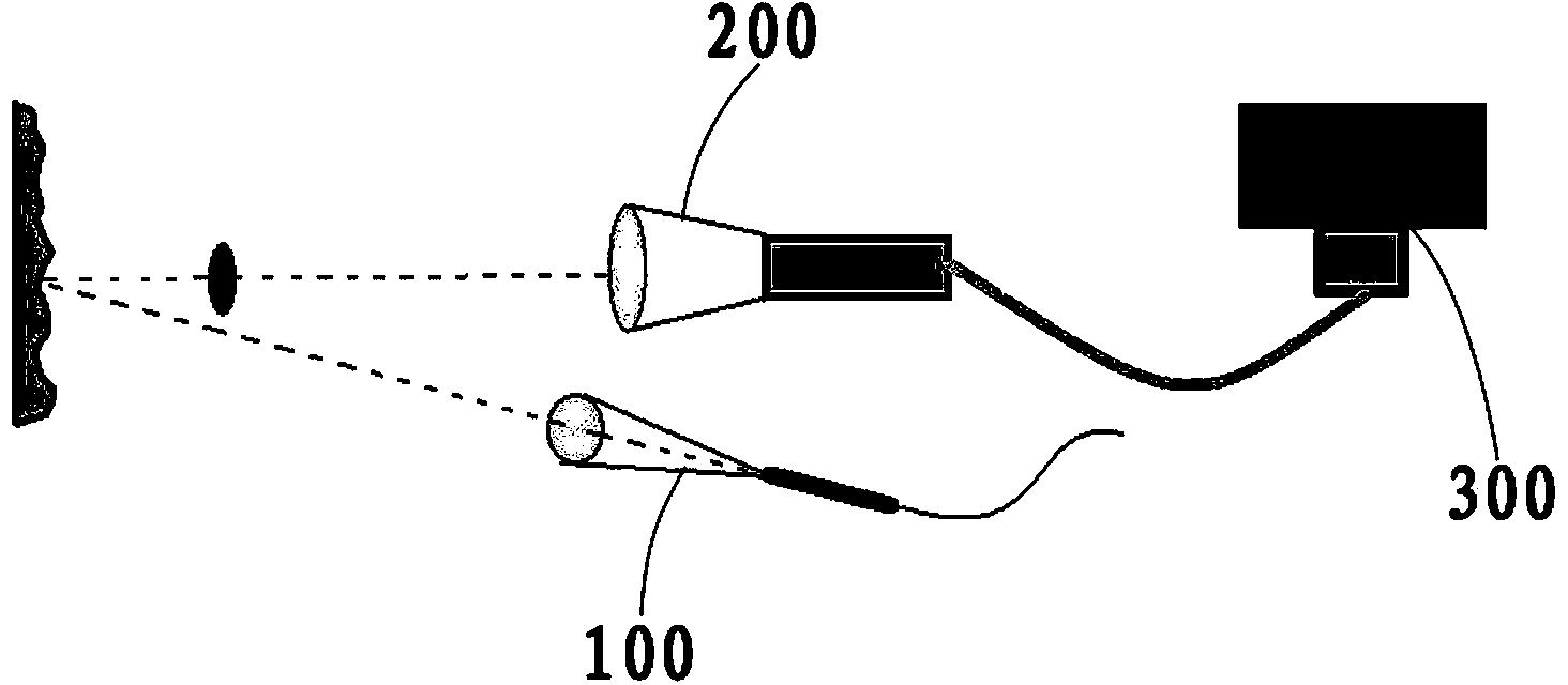
[0055] see figure 1 , The device used in the present invention mainly includes a laser 1, a high-speed camera 2 and a computer 3. Among them, the laser 1 is used to emit laser light and project it onto the surface of the target object to form speckles in space; the high-speed camera 2 is used to collect speckle scattered in space to obtain speckle images; the computer is used to store speckle images and perform Subsequent processing to realize voice signal reconstruction.

[0056] The present embodiment will be described in detail below in conjunction with the accompanying drawings.

[0057] see f...


PUM


Abstract

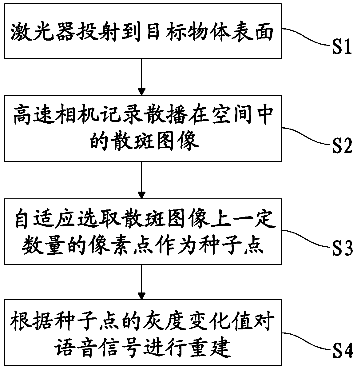
The invention discloses a voice signal reconstruction method based on laser speckle images. The voice signal reconstruction method based on the laser speckle images comprises steps of S1, enabling an optical laser to be projected on the surface of a target object and forming into surface speckles of the target object in space; S2, recording the speckles scattered in the space through a high speed camera, obtaining a group of speckle image sequences which are formed by continuous frame speckle images and storing the speckle image sequences into a computer to perform subsequent processing; S3, self-adaptively selecting a certain amount of pixel points in the speckle images to be served as seeded points; S4, working out vibration information on the surface of the target object according to a gray level change value, obtaining waveforms of sound waves which act on the surface of the target object and achieving reconstruction of voice signals. The voice signal reconstruction method based on the laser speckle images has the advantages of rapidly and conveniently exploring and processing the voice signals, meanwhile guaranteeing the high signal to noise ratio of an exploration result and the robustness to noise and being high in exploration sensitivity.

Description

technical field [0001] The invention relates to the field of laser speckle vibration measurement methods, in particular to a method for detecting micro-vibrations on the surface of an object based on laser speckle and then realizing voice signal reconstruction. Background technique [0002] Laser speckle is formed by the coherent light source generated by the laser irradiating the surface of a rough object, and the reflected light scatters and interferes with each other in space. [0003] Laser speckle has been widely used in crack detection in the medical field and engineering. With the development of science and technology, it is gradually being applied in the field of voice detection. In the early days of development, the method for voice detection was to use optical interferometers to collect and detect light reflected from windows. Such an approach has four major drawbacks: (1), all sound sources are detected simultaneously, so digital blind source signal separation te...

Claims


Application Information

Patent Timeline
IPC IPC(8): G10L25/00G01H9/00
Inventor 王程陈子仪王晓忠黄朝红付宏燕
Owner 奥谱微振(厦门)信息科技有限公司
Learn More