
High isolation, broadband indoor dual-polarized omnidirectional ceiling antenna

A high-isolation, ceiling-mounted antenna technology, applied in the direction of antenna grounding switch structure connection, radiation element structure, etc., can solve the problems of low isolation, aesthetic impact, and inconvenient wiring, and achieve cost reduction, beautiful appearance, and easy installation. convenient effect

Inactive Publication Date: 2017-01-11
GUANGZHOU TIANYI COMM TECH
View PDF8 Cites 0 Cited by
  • Summary
  • Abstract
  • Description
  • Claims
  • Application Information

AI Technical Summary

Problems solved by technology

[0006] At present, the existing dual-polarized omnidirectional ceiling antenna has the following disadvantages: 1. The isolation between polarization ports is not high, most of which are on the order of 20-25dB; 2. The bandwidth of the horizontally polarized omnidirectional antenna is narrow, Generally 1880-2500MHz; 3. The structure is complex and large, resulting in high cost and poor visual effect; 4. The wiring is inconvenient. The horizontally polarized coaxial feeder and the vertically polarized coaxial feeder are introduced into the antenna from different directions, affecting Beautiful, but also increases the trouble of engineering installation

Method used


Image

  • High isolation, broadband indoor dual-polarized omnidirectional ceiling antenna
  • High isolation, broadband indoor dual-polarized omnidirectional ceiling antenna
  • High isolation, broadband indoor dual-polarized omnidirectional ceiling antenna

Examples


Embodiment Construction

[0025] The present invention will be further described in the following embodiments in conjunction with the accompanying drawings.

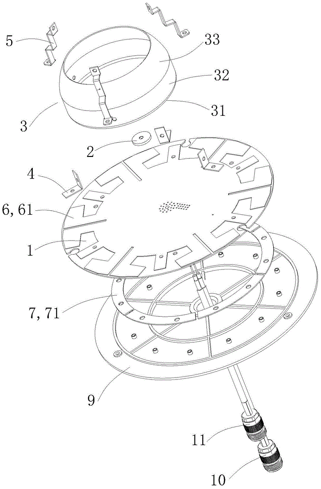
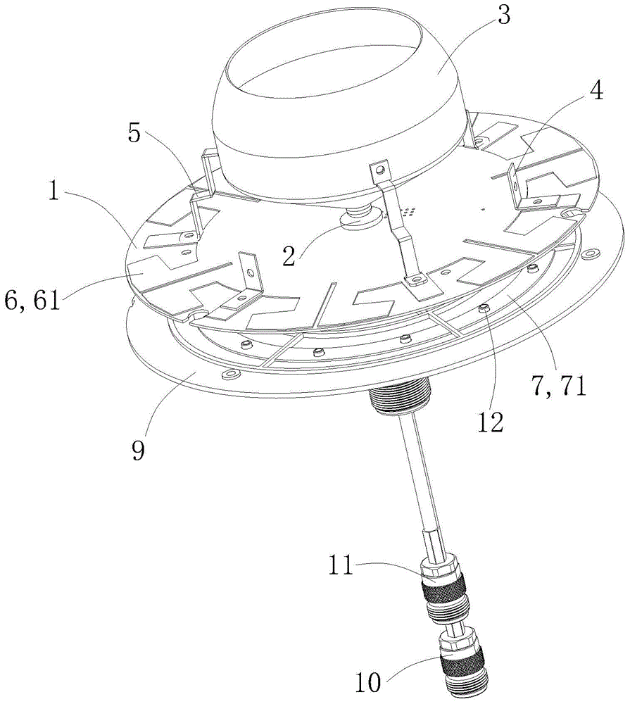
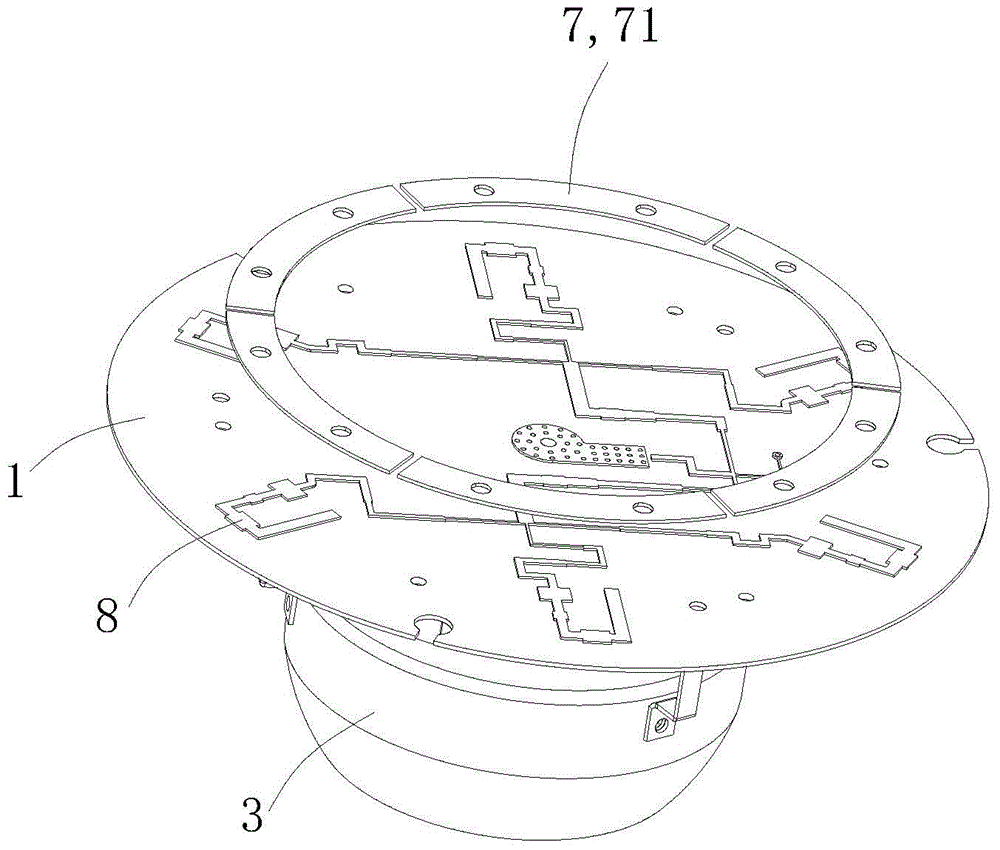
[0026] Such as Figure 1 to Figure 4 As shown, a high-isolation, broadband indoor dual-polarized omnidirectional ceiling antenna, including a vertically polarized antenna, a horizontally polarized antenna, and an antenna cover for encapsulating the two antennas (not shown in the figure) and antenna bottom cover9.

[0027] The vertically polarized antenna includes a common ground plate 1, a dielectric support seat 2, a vertically polarized radiator 3, three to six vertically polarized parasitic elements 4 bent at right angles, three to six short Tab 5. The common ground plate 1 adopts a microstrip structure in which the upper and lower surfaces are conductors filled with dielectric or air. The vertically polarized radiator 3 is used as a radiation oscillator, and is installed on the upper end of the common ground plate 1 through the dielectric ...


PUM


Abstract

The invention relates to a high-isolation and wideband indoor dual polarization omni-directional ceiling antenna which comprises a vertical polarization antenna and a horizontal polarization antenna together, wherein the vertical polarization antenna comprises a universal ground plate and a vertical polarization radiating body arranged at the upper end of the universal ground plate by virtue of a medium support base and a plurality of short circuit sheets, the horizontal polarization antenna comprises an annular array arranged at the upper surface of the universal ground plate and formed by a plurality of dipoles, a horizontal polarization parasitic element arranged below the universal ground plate and arranged at a certain distance from the universal ground plate, and a horizontal polarization feed network arranged at the lower surface of the universal ground plate. Compared with an existing like product, the high-isolation and wideband indoor dual polarization omni-directional ceiling antenna provided by the invention has the remarkable advantages of high isolation, wide band, simple structure, small volume, low cost, attractive appearance and the like.

Description

technical field [0001] The invention relates to a mobile communication indoor distribution antenna, in particular to a high-isolation, broadband indoor dual-polarized omnidirectional ceiling antenna. Background technique [0002] Modern mobile communication technology is changing with each passing day, and now MIMO (Multiple-Input Multiple-Output) technology is widely used in the new generation of mobile communication systems, such as WLAN, WiFi, WiMax, TD-SCDMA, LTE and so on. One of the important features of the MIMO technology is that the transmitting and receiving terminals of the wireless communication system are equipped with multiple antennas. [0003] Compared with the traditional single antenna (SISO) system, the wireless communication system adopting MIMO technology has obvious advantages. MIMO technology optimizes the transmission and reception of multi-path wireless channels as a whole. Through the algorithm of digital signal processing, the system capacity and ...

Claims


Application Information

Patent Timeline
Patent Type & Authority Patents(China)
IPC IPC(8): H01Q1/36H01Q1/50
Inventor 胡关平黄会兵方平阳谢米联谢革生谢三生
Owner GUANGZHOU TIANYI COMM TECH
Learn More