Calibrating device for large-range continuous optical path delay line
A technology of calibration device and delay line, applied in the field of calibration device of large-range continuous optical path delay line, can solve the problems of low precision, small delay range, large delay line connection loss, etc., and achieve high-precision measurement, high measurement accuracy, The effect of a large scanning range
- Summary
- Abstract
- Description
- Claims
- Application Information
AI Technical Summary
Problems solved by technology
Method used
Image

Examples
Embodiment 1
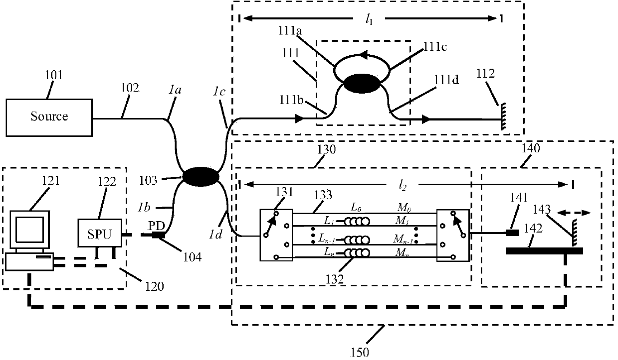
[0062] Example 1: Calibration device for reflective large-range continuous optical path delay line
[0063] The selection of main optoelectronic devices and their parameters are as follows:
[0064] (1) The central wavelength of the broadband light source 101 is 1550nm, the half-spectrum width>45nm, and the fiber output power>2mW;
[0065] (2) The working wavelength of the 2×2 coupler 103 is 1550nm, and the splitting ratio is 50:50;
[0066] (3) The working wavelength of the ring cavity 111 is 1550nm, and the insertion loss is ≤0.5dB;
[0067] (4) The working wavelength of the 1×8 optical switch 131 is 1550nm, and the insertion loss is ≤0.8dB;
[0068] (5) The extension fiber is G.652 ordinary fiber 132, and the model is SMF28e;
[0069] (6) The working wavelength of the optical collimator 141 is 1550nm, and the optical path scanning distance between it and the movable optical mirror 143 (the reflectivity is above 95%) is about 0-200mm, and the average insertion loss is 3....
Embodiment 2
[0087] Example 2: Calibration device for transmission-type large-range continuous optical delay line
[0088] A calibration device for a transmission-type long-range continuous optical delay line is as follows: Figure 5 As shown, compared with Embodiment 1, most of the photoelectric device parameters are exactly the same, the difference is that in Embodiment 2, the continuous optical path scanning device adopts a group of optical collimators, a group of optical mirrors and a program-controlled displacement The length of the periodic delayer is changed when used with the station.
[0089] in such as Figure 5 In the shown structure, 1×8 optical switches are also used to form an 8-channel optical fiber delay line, and 8 discrete delay values can be obtained. Such as Image 6 Shown is the measurement process of the delay of the fiber delay line, as follows:
[0090] (1) Turn on the instrument, reset the optical switch, and reset the program-controlled stage to zero;
[00...
PUM
| Property | Measurement | Unit |
|---|---|---|
| Center wavelength | aaaaa | aaaaa |
| Diameter | aaaaa | aaaaa |
| Length | aaaaa | aaaaa |
Abstract
Description
Claims
Application Information
 - Generate Ideas
- Intellectual Property
- Life Sciences
- Materials
- Tech Scout
- Unparalleled Data Quality
- Higher Quality Content
- 60% Fewer Hallucinations
Browse by: Latest US Patents, China's latest patents, Technical Efficacy Thesaurus, Application Domain, Technology Topic, Popular Technical Reports.
© 2025 PatSnap. All rights reserved.Legal|Privacy policy|Modern Slavery Act Transparency Statement|Sitemap|About US| Contact US: help@patsnap.com