Self-balance control method of movable type inverted pendulum system and self-balance vehicle intelligent control system

A control method and inverted pendulum technology, applied in the direction of program control manipulators, manufacturing tools, manipulators, etc., can solve the problems of complicated signal control, high manufacturing cost, affecting the overall quality of self-balancing vehicles, etc.

Inactive Publication Date: 2014-04-30
SHANGHAI CHUANGHUI ROBOT TECH
View PDF13 Cites 19 Cited by
  • Summary
  • Abstract
  • Description
  • Claims
  • Application Information

AI Technical Summary

Problems solved by technology

The inverted pendulum used in the experiment is usually abstracted into a simple linear inverted pendulum and a simple rotating inverted pendulum in order to reduce the impact factor, which simplifies the research of the problem scientifically and provides a basis for the application of the inverted pendulum system in the device in reality. Conditions, but the inverted pendulum is a complex system after all, especially the inverted pendulum system in the moving state, the signal control related to its stability is more complicated and unstable
[0003] There are still problems in the balance control of the existing sports inverted pendulum system: the linear inverted pendulum can only move along a fixed track, and the rotating inverted pendulum can only move in a circular arc with a fixed origin. These inverted pendulum devices need to be limited. Position device and protection circuit module increase the complexity of the balance control algorithm. The range of movement of the inverted pendulum system is mainly limited to the fixed guide rail or the range of the horizontal plane, which is not in line with the actual life and engineering applications. Laboratory is used in scientific experiments and teaching, it is difficult to enter people's life and work
However, although the balance control algorithm of the conventional sports inverted pendulum system can also realize the autonomous balance of the self-balancing vehicle, there are often small disturbances, which have a bad impact on the driving comfort of the self-balancing vehicle.
The conventional mobile inverted pendulum system is not closely integrated with the actual needs and engineering applications. The control strategy basically adopts a general-purpose data processing module without a specially customized control algorithm strategy module. ...

Method used


Image

  • Self-balance control method of movable type inverted pendulum system and self-balance vehicle intelligent control system
  • Self-balance control method of movable type inverted pendulum system and self-balance vehicle intelligent control system
  • Self-balance control method of movable type inverted pendulum system and self-balance vehicle intelligent control system

Examples


Embodiment 1

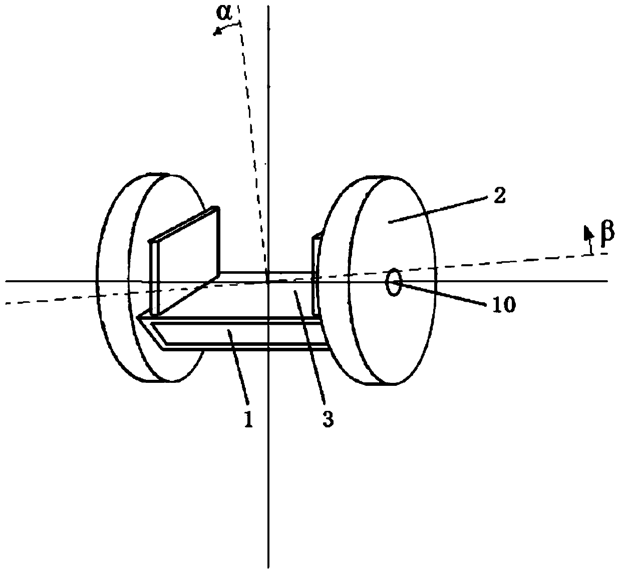
[0063] In this example, see Figure 1 ~ Figure 4 , self-balancing car intelligent control system, mainly including power supply system 9, signal acquisition subsystem 5, signal finishing subsystem 6, signal processing subsystem 7 and control system 8, will be used as the controlled pendulum of the mobile inverted pendulum system According to the detection result of the controlled parameters of the frame body 1, the control signal is applied to the controlled wheel 2 according to the predetermined target, so that the closed-loop control of the balanced and stable state of the frame body 1 is realized by driving the wheel 2, and the power supply system 9 For supplying power to various systems and electronic devices, the signal acquisition subsystem 5 includes a gyroscope 11, an acceleration sensor 12, a HALL sensor 13 and an acquisition control chip 14. The signal acquisition subsystem 5 is installed on the vehicle frame body 1, wherein the gyroscope 11 corresponds to the wheel ...

Embodiment 2

[0082] This embodiment is basically the same as Embodiment 1, especially in that:

[0083] In this example, see Figure 5 with Image 6 , as the single-wheel intelligent self-balancing vehicle of the detection and control target of the intelligent self-balancing vehicle in this embodiment, its wheel 2 is arranged at the middle position of the vehicle frame platform 3, and the vehicle frame platform 3 is respectively located on the left and right sides of the wheel 2 In addition, an inertial element is provided to maintain the left and right balance of the wheel 2. The inertial element is rotatably connected to the frame body 1 through a mandrel, and the mandrel of the inertial element is parallel to the axis of the wheel axle 10. The mandrel is driven by a drive motor 18 The control system 8 controls the in-wheel motor 4 to drive the wheel 2 to rotate forward or reversely, and controls the rotation speed of the driving motor 18 to regulate the high-speed rotation of the inert...

Embodiment 3

[0085] This embodiment is basically the same as Embodiment 1, especially in that:

[0086] In this embodiment, as the two-wheeled intelligent self-balancing vehicle of the detection and control target of the intelligent self-balancing vehicle in this embodiment, each wheel 2 is separately equipped with an inertial element that maintains the left and right balance of the corresponding wheel 2, and the inertial element passes through the mandrel It is rotatably connected with the frame body 1, and the mandrel of the inertial element is parallel to the axis of the corresponding wheel axle 10. The mandrel is driven by the driving motor 18, which then drives the inertial element to rotate at high speed. The control system 8 controls the rotation of the driving motor 18 The speed is used to control the high-speed rotation of the inertial element to generate the moment of inertia, which constrains the left and right deflection of the wheel 2 . In the present invention, each wheel 2 i...


PUM


Abstract

The invention discloses a self-balance control method of a movable type inverted pendulum system. State signals of the movable type inverted pendulum system are collected, the filter processing data method with the combination of a wavelet topology network and a regulator is adopted, a signal fusion technology is used for assistance, input data, middle data and output data of each filter node where effective values of the wavelet network enter are continuously adjusted, the controlled system control number output by the system is completed, the stability and the reliability of work of an inverted pendulum are improved, and the driving and riding stability, safety and comfort of an electric riding tool based on the inverted pendulum system are improved. The invention discloses a self-balance vehicle intelligent control system. By the adoption of a filter processing unit and a signal fusion unit, the capacity of combined control and information feedback of an electrical system and a mechanical system are improved, tiny disturbance generated in the movement process of a self-balance vehicle is reduced, the intelligent degree is improved, the self-balance vehicle intelligent control system is convenient and easy to use, comfortable, stable and capable of reducing cost and improving the cost performance.

Description

technical field [0001] The present invention relates to an automatic control system and a control method for a mobile robot, in particular to an autonomous balance control system and a control method for a vehicle, which is applied in the technical field of inverted pendulum control and is suitable for applying control strategies and carrying out various control experiments Platform, especially suitable for the control field of robot-assisted people-carrying devices, especially for self-balancing vehicles, including two-wheeled vehicles, unicycles, large-wheeled vehicles or small-wheeled vehicles, suitable for environmental protection travel, human transportation, outdoor Fitness, beach surfing, convenient walking aid, personalized travel, police patrol, military mobility, mobile camera photography, mobile viewing, fast arrival, small piece delivery, entertainment and leisure, ceremonial guard of honor, planetary transportation, planetary surface detection and scientific experi...

Claims


Application Information

Patent Timeline
IPC IPC(8): B25J9/18
Inventor 应亦凡魏庆前应卫强
Owner SHANGHAI CHUANGHUI ROBOT TECH
Why Eureka
Try Eureka