Self-balance control method of movable type inverted pendulum system and self-balance vehicle intelligent control system
A control method and inverted pendulum technology, applied in the direction of program control manipulators, manufacturing tools, manipulators, etc., can solve the problems of compatibility and software interface incompatibility, difficulty, and increase the difficulty of installation of automatic balance car equipment.
- Summary
- Abstract
- Description
- Claims
- Application Information
AI Technical Summary
Problems solved by technology
Method used
Image
Examples
Embodiment 1
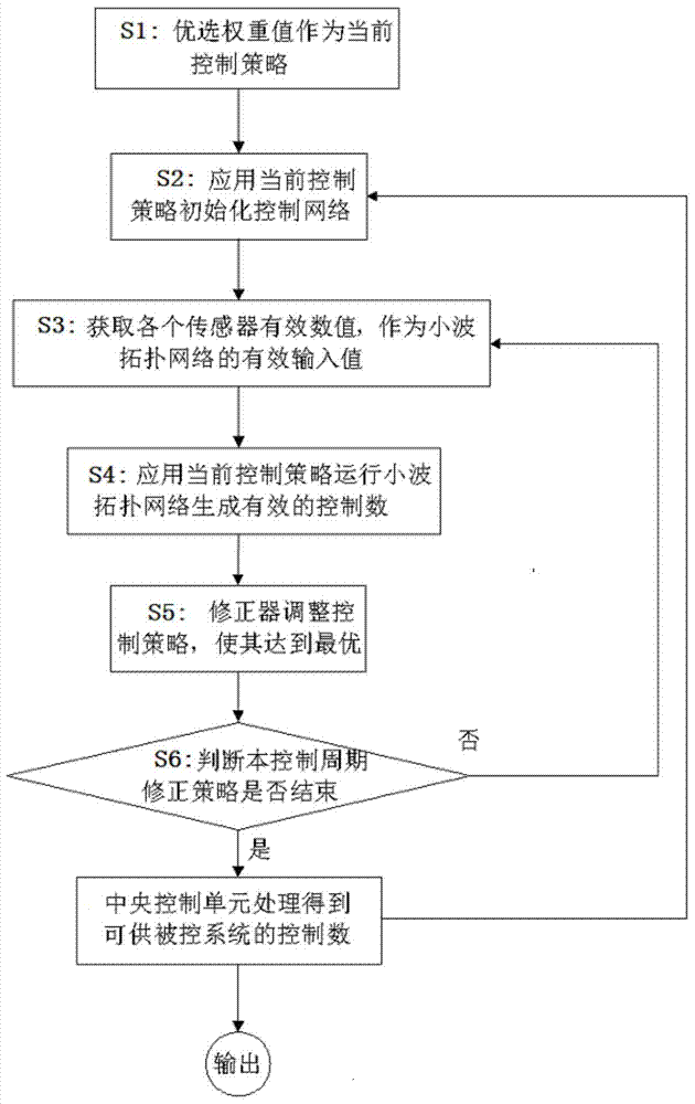
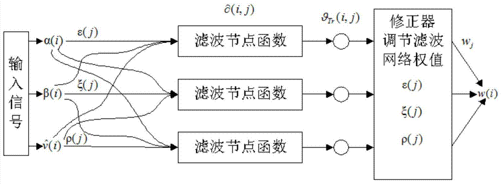
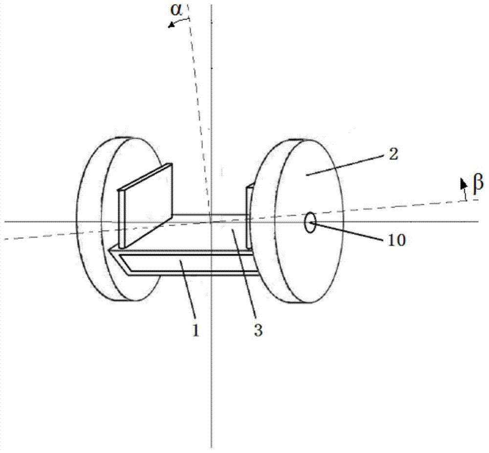
[0063] In this example, see Figure 1 ~ Figure 4 , self-balancing car intelligent control system, mainly including power supply system 9, signal acquisition subsystem 5, signal finishing subsystem 6, signal processing subsystem 7 and control system 8, will be used as the controlled pendulum of the mobile inverted pendulum system According to the detection result of the controlled parameters of the frame body 1, the control signal is applied to the controlled wheel 2 according to the predetermined target, so that the closed-loop control of the balanced and stable state of the frame body 1 is realized by driving the wheel 2, and the power supply system 9 For supplying power to various systems and electronic devices, the signal acquisition subsystem 5 includes a gyroscope 11, an acceleration sensor 12, a HALL sensor 13 and an acquisition control chip 14. The signal acquisition subsystem 5 is installed on the vehicle frame body 1, wherein the gyroscope 11 corresponds to the wheel ...
Embodiment 2
[0082] This embodiment is basically the same as Embodiment 1, especially in that:
[0083] In this example, see Figure 5 with Image 6 , as the single-wheel intelligent self-balancing vehicle of the detection and control target of the intelligent self-balancing vehicle in this embodiment, its wheel 2 is arranged at the middle position of the vehicle frame platform 3, and the vehicle frame platform 3 is respectively located on the left and right sides of the wheel 2 In addition, an inertial element is provided to maintain the left and right balance of the wheel 2. The inertial element is rotatably connected to the frame body 1 through a mandrel, and the mandrel of the inertial element is parallel to the axis of the wheel axle 10. The mandrel is driven by a drive motor 18 The control system 8 controls the in-wheel motor 4 to drive the wheel 2 to rotate forward or reversely, and controls the rotation speed of the driving motor 18 to regulate the high-speed rotation of the inert...
Embodiment 3
[0085] This embodiment is basically the same as Embodiment 1, especially in that:
[0086] In this embodiment, as the two-wheeled intelligent self-balancing vehicle of the detection and control target of the intelligent self-balancing vehicle in this embodiment, each wheel 2 is separately equipped with an inertial element that maintains the left and right balance of the corresponding wheel 2, and the inertial element passes through the mandrel It is rotatably connected with the frame body 1, and the mandrel of the inertial element is parallel to the axis of the corresponding wheel axle 10. The mandrel is driven by the driving motor 18, which then drives the inertial element to rotate at high speed. The control system 8 controls the rotation of the driving motor 18 The speed is used to control the high-speed rotation of the inertial element to generate the moment of inertia, which constrains the left and right deflection of the wheel 2 . In the present invention, each wheel 2 i...
PUM
 Abstract
Description
Claims
Application Information
 - R&D
- Intellectual Property
- Life Sciences
- Materials
- Tech Scout
- Unparalleled Data Quality
- Higher Quality Content
- 60% Fewer Hallucinations
Browse by: Latest US Patents, China's latest patents, Technical Efficacy Thesaurus, Application Domain, Technology Topic, Popular Technical Reports.
© 2025 PatSnap. All rights reserved.Legal|Privacy policy|Modern Slavery Act Transparency Statement|Sitemap|About US| Contact US: help@patsnap.com


