Mask device as well as system and method for manufacturing mask device

A mask and mask plate technology, applied in the field of masks, can solve the problems of frame deformation, difficult access to metal plates, stress deformation, etc., and achieve the effect of improving accuracy

Inactive Publication Date: 2014-04-30
EVERDISPLAY OPTRONICS (SHANGHAI) CO LTD
View PDF5 Cites 27 Cited by
  • Summary
  • Abstract
  • Description
  • Claims
  • Application Information

AI Technical Summary

Problems solved by technology

[0003] In the early OLED manufacturing process, due to the small size of the substrate, the method of stretching the net was a single mask. This method cannot effectively stretch all the mask array holes to the required position; as the size of the substrate continues to increase Enlargement, due to the limitation of color mixing yield and metal plate, this method can no longer be used
Obviously, the disadvantage of this kind of small-generation OLED metal mask stretching method is: due to stress deformation, the method of stretching the net with a single mask cannot effectively control the position of each cell, and cannot completely stretch the mask array holes. to the desired location
If this method is applied to large-generation substrates, it will cause a huge netting error
Moreover, the sub-40um metal sheet required to make this mask is not easy to obtain
[0004] Nowadays, OLED mask stretching technology with large-generation substrate size has been developed into the method of split mask stretching, but this method still cannot fully meet the demand for color mixing yield, and excessive stretching tension will make The mask frame has slight deformation; and is limited by the mask manufacturer's production accuracy of the whole segmented single-piece mask, so it is impossible to actually stretch the mask to the position where the evaporation machine needs to be compensated
The disadvantage of the large-generation OLED metal mask stretching method is that although the split single-piece mask can perform more accurate netting than the single-sheet mask, it cannot effectively control each unit in the split single-chip mask. The position of the grid and the mask is completely stretched to the required position
In order to prevent the sagging of the split single-piece mask after stretching, a larger stretching force is often used to respond, but excessive stretching force will cause slight deformation of the frame after stretching
And, likewise, the sub-40um sheet metal required to make this mask is not readily available

Method used


Image

  • Mask device as well as system and method for manufacturing mask device
  • Mask device as well as system and method for manufacturing mask device
  • Mask device as well as system and method for manufacturing mask device

Examples


Embodiment Construction

[0065] Embodiments of the mask device, the system and method for manufacturing the mask device of the present invention will be described below with reference to the accompanying drawings. It should be noted that the following descriptions about the embodiments are only for explaining the gist and spirit of the present invention, and are not intended to directly limit the present invention. At the same time, in the following embodiments and accompanying drawings, elements not directly related to the present invention have been omitted and not shown; and the dimensional relationship between the elements and the number of elements in the accompanying drawings are only for easy understanding, not for limitation Actual scale, actual size and actual quantity.

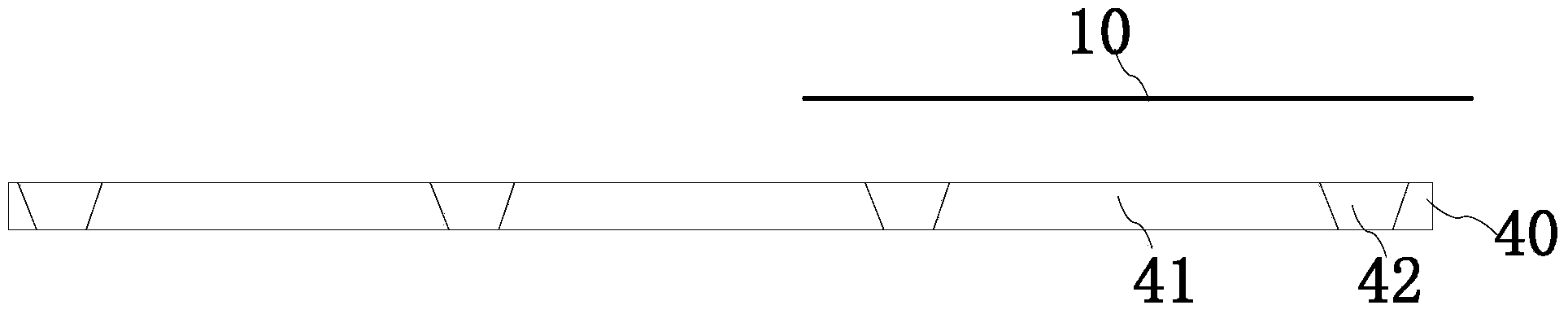
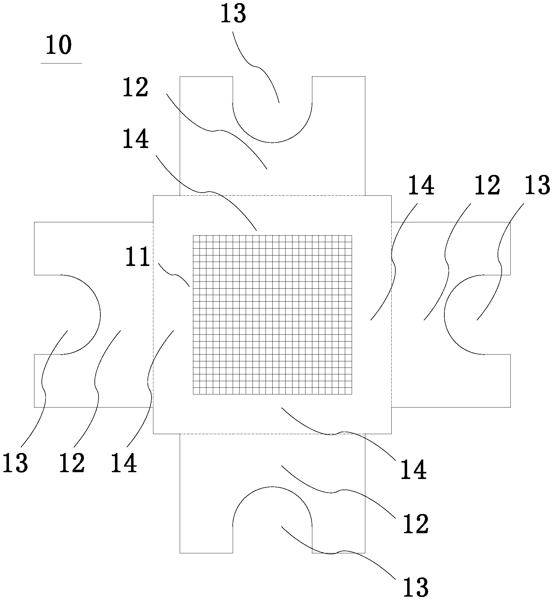
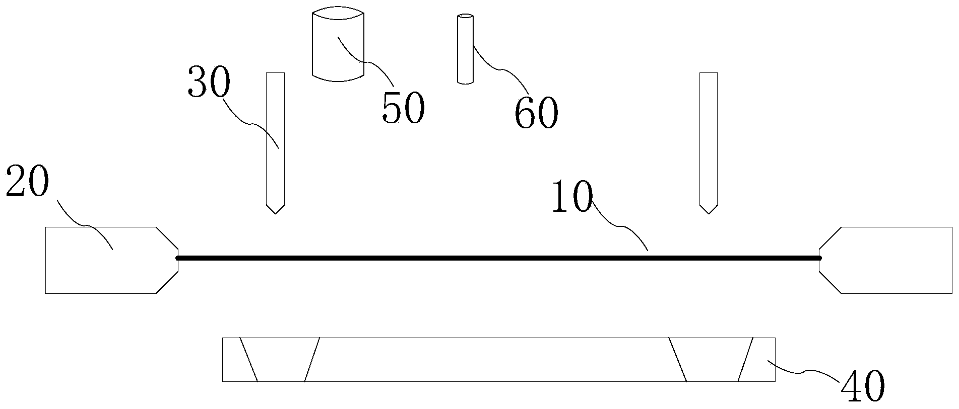
[0066] figure 1 A partially exploded schematic view of a mask device according to an embodiment of the present invention is shown. Such as figure 1 As shown, the mask device of the present invention includes a mask bracke...


PUM

PropertyMeasurementUnit
lengthaaaaaaaaaa
widthaaaaaaaaaa

Abstract

The invention provides a mask device as well as a system and a method for manufacturing the mask device. The mask device comprises a mask tray and a plurality of mask plates on one side of the mask tray, wherein the mask tray comprises a plurality of support ribs; a plurality of grid openings which are arrayed in matrix are formed among the plurality of support ribs; each mask plate comprises a mask hole array and a plurality of fixed parts outward extending from the mask hole array; the fixed parts are used for connecting the support ribs of the mask tray; the mask hole array of one mask plate corresponds to one grid opening on the mask tray. By adopting the invention, the mask plates and the mask tray are simultaneously improved, and the traditional mask tray is designed into grid shape with support ribs in the middle instead of big openings; the plurality of mask plates respectively correspond to each grid and are respectively unfolded so that micro-distortion caused by large tension can be avoided and the mask plates can be more accurately unfolded to correct positions.

Description

technical field [0001] The invention relates to a mask used in the manufacturing process of a display, in particular to an OLED small metal mask device, a system and a method for manufacturing the mask device. Background technique [0002] OLED (Organic Light-Emitting Diode, Organic Light-Emitting Diode) is a brand-new display device. It uses a technology that can emit light by itself when an applied voltage is applied. It is a popular research topic in the field of photoelectrochemistry and material science in recent years. , is also a research hotspot in the current international display technology. It will become a strong competitor of LCD that cannot be underestimated, and it is also a new generation of display technology recognized by the display industry as the most likely to replace LCD. The materials used in OLED devices can be organic small molecules or polymer polymers, so there is a wide range of choices. Through the design, assembly and tailoring of organic molec...

Claims


Application Information

Patent Timeline
Patent Type & Authority Applications(China)
IPC IPC(8): C23C14/04B23K28/02B23K26/22B23K26/38
CPCC23C14/024C23C14/042C23C14/12H10K71/00
Inventor 黄俊允
Owner EVERDISPLAY OPTRONICS (SHANGHAI) CO LTD
Why Eureka
Try Eureka