Electrolytic tinning liquid

An electro-tin plating solution and electro-tin technology, applied in the field of electro-tin plating, can solve problems such as equipment corrosion, empty plating product inflow, thickness fluctuation, etc., and achieve the effect of improving quality

Active Publication Date: 2014-04-30
GUANGDONG GUANGHUA SCI TECH
View PDF8 Cites 12 Cited by
  • Summary
  • Abstract
  • Description
  • Claims
  • Application Information

AI Technical Summary

Problems solved by technology

However, if the pH value of this electroplating method is too low, it will cause corrosion to some equipment
[0004] Although the above-mentioned prior art has solved the duplex problem of electronic components, the distribution of current is very uneven in the process of tin plating, especially in the barrel plating process, and the current around the cathode terminal (generally conductive ball) is large, and the distance from the conductive ball is relatively large. Due to the resistance of the far steel balls and electronic components and the volume of the barrel, the current is relatively small
Therefore, the steel balls and electronic components near the conductive ball are electroplated tin faster, and they are easy to accumulate together and stick to the conductive ball to form "caking", but the electronic components inside the agglomeration cannot be completely covered with tin
The agglomeration of conductive balls, steel balls, and electronic components causes a drop in yield, and may cause empty-plated products to flow into qualified products. The possibility of empty-plated products being picked out is almost zero, causing serious product hidden dangers
And the inhomogeneity of the current leads to a certain degree of fluctuation in the thickness of the product, which reduces the consistency of the product

Method used


Image

  • Electrolytic tinning liquid
  • Electrolytic tinning liquid
  • Electrolytic tinning liquid

Examples


Embodiment 1

[0050] A kind of electroplating tin bath of the present embodiment comprises following raw material components:

[0051] (A) stannous salt: stannous methanesulfonate, the concentration of stannous ion is 13g / L;

[0052] (B) Acid: methanesulfonic acid, the concentration is 50g / L;

[0053] (C) Surfactant: polyoxyethylene laurate ((C) 2 h 4 O) 10 ) ester, the concentration is 10g / L;

[0054] (D) Current dispersant: 2-ethylene glutaric acid, the concentration is 0.01g / L;

[0055] (E) Conductive salt: sodium phenolsulfonate, the concentration is 10g / L;

[0056] (F) pH regulator: KOH to adjust the pH to 3.2.

[0057] The electroplating process is as follows:

[0058] 1. Prepare the tin plating solution according to the ratio of the above raw materials;

[0059] 2. Filter, circulate and freeze the plating solution with a filter (filter element no more than 5 μm) and a freezer;

[0060] 3. Control the ratio of steel ball and plated parts;

[0061] 4. Rack plating and barrel ...

Embodiment 2-11

[0082] The raw material composition of the tin electroplating solution of embodiment 2-11 is as shown in table 1, and electroplating condition and test item are identical with embodiment 1, and result is as follows:

[0083] Table 1

[0084]

[0085]

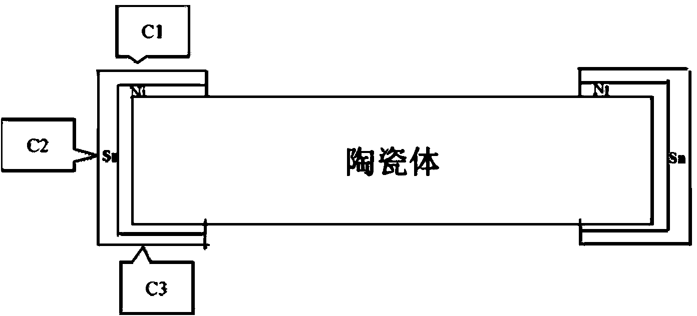
[0086] Δ indicates that the test result is good; X indicates that the test result is not good; the smaller the bonding rate, the higher the yield, generally not more than 10%; the HullCell test result indicates the length of bright and sub-bright areas, the length of bright and sub-bright The larger the range of the bright area, the wider the current window; the coating thickness range of 4-10 μm is qualified, and the closer the thickness of C1, C2, and C3 is, the better the throwing ability is; the voltage is lower than 1 / 2 of the current value. Low means less power consumption (voltage lower than 6V).

[0087] Through the comparison of Examples 1-11, it can be found that Examples 3 and 4 have lower voltage, the conducti...


PUM

PropertyMeasurementUnit
diameteraaaaaaaaaa

Abstract

The invention discloses electrolytic tinning liquid, which comprises the following raw material components: (A) stannous salt of which the stannous tin ion concentration is 1-100g/L, (B) acid of which the total concentration is 10-200g/L, (C) a surfactant selected from one or more of nonionic surfactants of which the structural formula are as follows: R1COO(C2H4O)nH and R2S(C2H4O)mH, being 1-20g/L in the total concentration, (D) a current dispersing agent which is selected from an unsaturated bond-containing dicarboxylic acid derivative or a salt thereof and is 0.01-2g/L in concentration, (E) conducting salt of which the concentration is 2-10g/L, and (F) a pH regulating agent for regulating the pH value of the electrolytic tinning liquid to 2.0-4.0. By adopting the electrolytic tinning liquid, the current distribution among steel balls, electronic elements and conducting balls in an electrolytic tinning drum can be optimized, the steel balls and the electronic elements are prevented from being bonded on the conducting balls by means of electroplating, and the quality of electrolytic tinning products is improved.

Description

technical field [0001] The invention relates to the technical field of tin electroplating, in particular to a tin electroplating solution capable of improving the current distribution of tin electroplating. Background technique [0002] With the development of electronic equipment, small size, multi-function, high performance, and easy operation have become the development trend of electronic components. In order to solder electronic components to the device more easily, tinning is required on the electronic components to improve solderability. Due to the small size of electronic components, it is more likely to cause the problem of two components sticking together, referred to as "duplex", and will be replaced by "duplex" below. The production of duplexes greatly reduces the qualified rate of products. Traditionally, the duplex rate (the amount of duplex products is higher than the total amount of products) of stannous sulfate electroplating is very high. For this reason,...

Claims


Application Information

Patent Timeline
Patent Type & Authority Applications(China)
IPC IPC(8): C25D3/30
Inventor 任秀斌肖定军裘宇王植材
Owner GUANGDONG GUANGHUA SCI TECH
Why Eureka
Try Eureka