Vehicle magneto-rheological oil gas suspension damping valve

An oil-pneumatic suspension and magneto-rheological technology, applied in the direction of springs, shock absorbers, spring/shock absorbers, etc., can solve the problems of easy damage of sensors, lower viscosity, lower reliability of shock absorbers, etc., to facilitate heat dissipation , large damping force and small outer diameter

Inactive Publication Date: 2014-04-30
ANHUI LIUGONG CRANE
View PDF11 Cites 5 Cited by
  • Summary
  • Abstract
  • Description
  • Claims
  • Application Information

AI Technical Summary

Problems solved by technology

[0004] For the current magneto-rheological oil-pneumatic suspension, due to the large piston area of ​​the cylinder of the oil-pneumatic suspension, the liquid flow through the damping valve will be large. When the damping valve is built in, it will encounter problems when driving on bad roads. Heat dissipation problem, too high oil temperature will cause the viscosity to decrease, affect the performance of the gas in the accumulator, and may damage the electromagnetic coil, thereby affecting the external characteristics of the oil-gas suspension, and in the existing vehicle magneto-rheological reduction In the vibration system, there are two ways to realize the relative movement speed of the body and the wheel, the relative displacement mode and the relative acceleration mode. One or more acceleration sensors are configured in the system; no matter which method is used, configuring the sensor alone will increase the cost of the system, and the sensor is directly exposed to the external environment and is easily damaged, thereby reducing the reliability of the system
[0005] The CN1593962A invention patent published by China for the first time pre-announced a vehicle suspension shock absorber with relative speed self-sensing function. An excitation coil is wound on the head, and an induction coil is installed in the

Method used


Image

  • Vehicle magneto-rheological oil gas suspension damping valve
  • Vehicle magneto-rheological oil gas suspension damping valve
  • Vehicle magneto-rheological oil gas suspension damping valve

Examples


Embodiment Construction

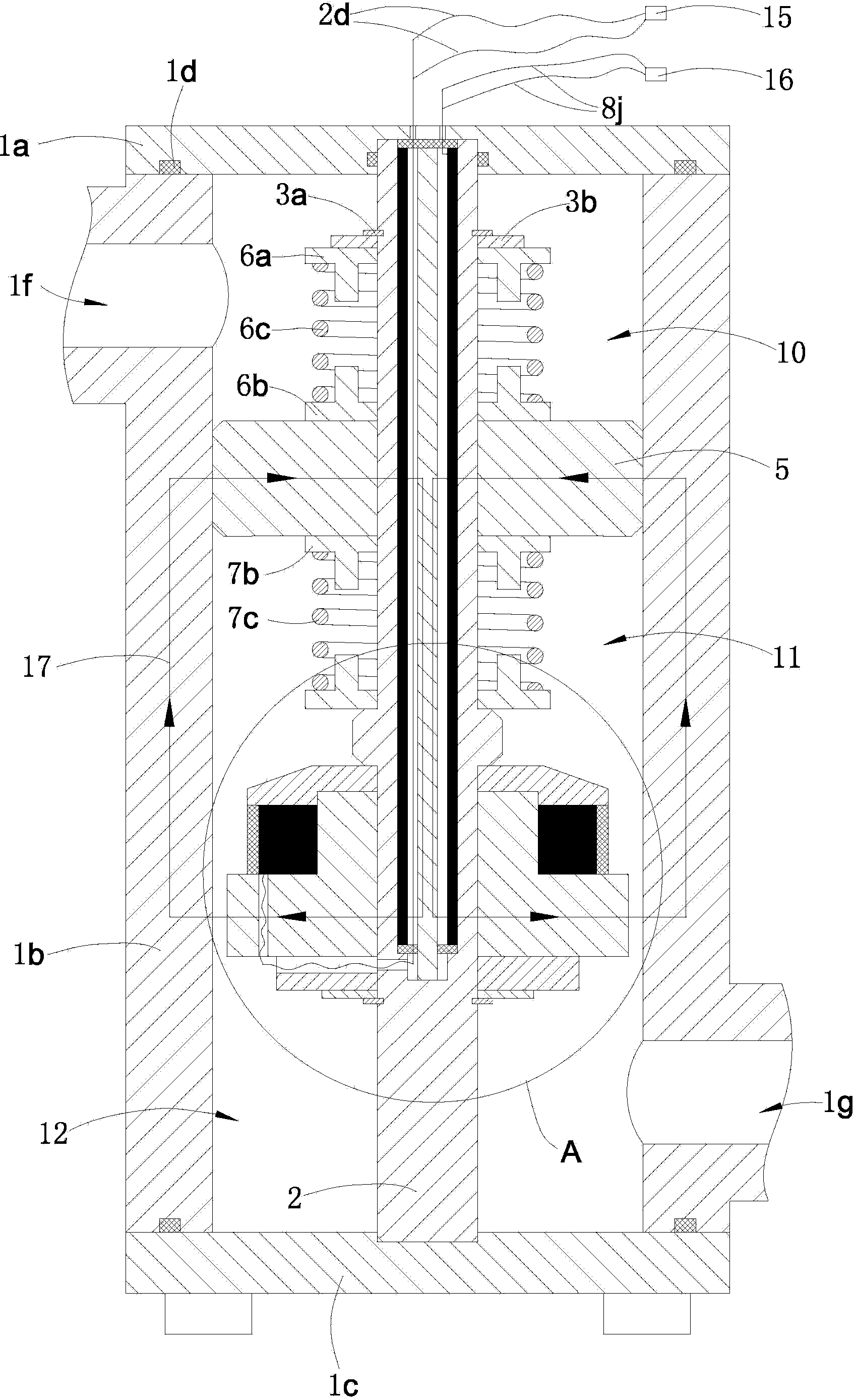
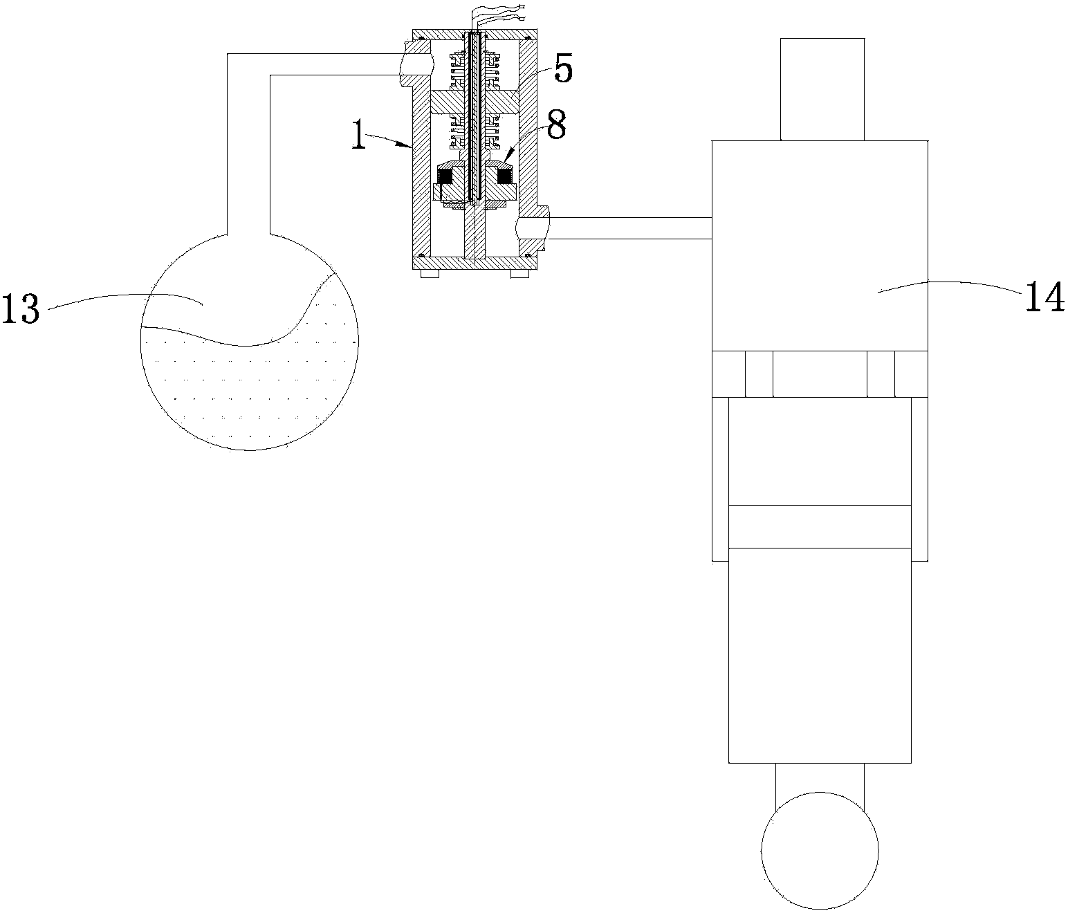
[0028] Such as Figures 1 to 2 shown

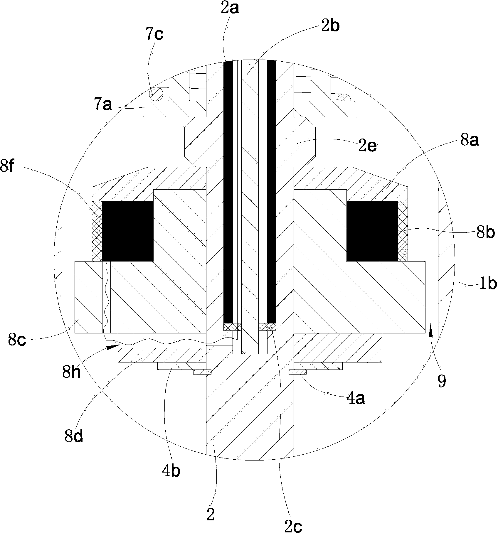
[0029] The damping valve includes a valve body 1, a mounting pipe 2, a floating piston 5, an upper limit assembly, a lower limit assembly, an upper fixing member, a fixed valve core 8 and a lower fixing member.

[0030] The valve body 1 includes an upper cover plate 1a, a sleeve 1b and a lower cover plate 1c, a sealing ring 1d is arranged between the upper cover plate 1a and the sleeve 1b, and a sealing ring 1d is also arranged between the lower cover plate 1c and the sleeve 1b , The upper cover 1a and the lower cover 1c are made of extremely low magnetic permeability materials; the sleeve 1b is made of high magnetic permeability materials.

[0031] An installation pipe 2 is fixed between the upper cover plate 1a and the lower cover plate 1c. An induction coil 2a and a winding rod 2b are arranged inside the installation pipe 2. The induction coil 2a is wound outside the winding rod 2b. The upper and lower ends of the induction coil 2a ar...


PUM


Abstract

The invention provides a vehicle magneto-rheological oil gas suspension damping valve. The vehicle magneto-rheological oil gas suspension damping valve comprises a valve body with an inner cavity, an installation pipe and a floating piston, wherein the installation pipe is fixedly placed in the valve body, an induction coil and a winding rod are arranged in the installation pipe, the induction coil is wound around the winding rod, and the floating piston is installed on the installation pipe. An upper fixing piece, a middle fixing piece and a lower fixing piece are arranged on the outer wall of the installation pipe, the floating piston is arranged between the upper fixing piece and the middle fixing piece, an upper limiting assembly is placed between the floating piston and the upper fixing piece, a lower limiting assembly is placed between the floating piston and the middle fixing piece, and the installation pipe is further provided with a fixed valve element. The damping valve is integrated with a velocity sensor, and therefore the damping valve is high in reliability. The vehicle magneto-rheological oil gas suspension damping valve can automatically sense the vibration velocity of wheels relative to a vehicle body, and corresponding damping adjustment can be carried out according to voltage generated by the induction oil.

Description

technical field [0001] The invention relates to a damping element of an automobile magneto-rheological oil-gas suspension system, in particular to a damping valve of a vehicle magneto-rheological oil-gas suspension. Background technique [0002] The traditional oil-pneumatic suspension system is designed according to a specific road condition and vehicle operating state, and its damping characteristics are not adjustable. However, due to the complex and changeable road surface conditions, the suspension system with fixed damping characteristics cannot be adjusted according to the road surface conditions. Conditions and the state of the vehicle adjust its damping accordingly. When the road conditions and vehicle state exceed its design conditions, the damping effect of the suspension will be greatly reduced, affecting the ride comfort and safety of the vehicle. [0003] Magneto-rheological oil-air suspension uses the rheological characteristics of magnetorheological fluid tha...

Claims


Application Information

Patent Timeline
IPC IPC(8): F16F9/34
Inventor 王勋王充
Owner ANHUI LIUGONG CRANE
Why Eureka
Try Eureka