Mixed waste disposal system

A garbage treatment system and garbage technology, applied in sludge treatment, biological sludge treatment, water/sludge/sewage treatment, etc., can solve the problem of increasing the actual treatment amount of leachate, low moisture content calorific value, and reducing sludge Dealing with issues such as effectiveness

Inactive Publication Date: 2014-04-30
南京溧水石湫机场科技工业园开发有限公司
View PDF5 Cites 11 Cited by
  • Summary
  • Abstract
  • Description
  • Claims
  • Application Information

AI Technical Summary

Problems solved by technology

[0004] After submitting the above text, the applicant is still committed to the further optimization and improvement of its structure and process; the applicant found in the later continuous research and development that the above system design still uses the traditional classification treatment method, that is, the traditional sludge The treatment pool is only used as a sedimentation, storage and transfer warehouse, so additional sludge storage areas and incineration processes must be set up separately for fermentation and incineration treatment, which often leads to an inability to achieve an effective balance between its site occupancy rate and fermentation efficiency. At the same time, the additional sludge treatment equipment also leads to the reduction of the work efficiency of the enterprise
In fact, some manufacturers have also considered the mixed waste treatment process, and directly discharge the municipal sludge to the crushing unit for direct mixing and crushing with domestic waste, and combine them for fermentation; however, due to the Or the characteristics of very little open water. On

Method used


Image

  • Mixed waste disposal system
  • Mixed waste disposal system
  • Mixed waste disposal system

Examples


Embodiment Construction

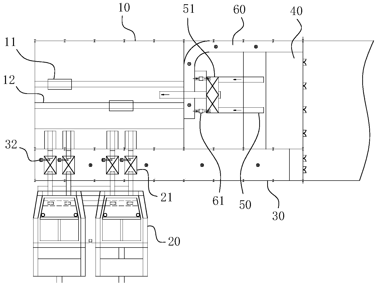
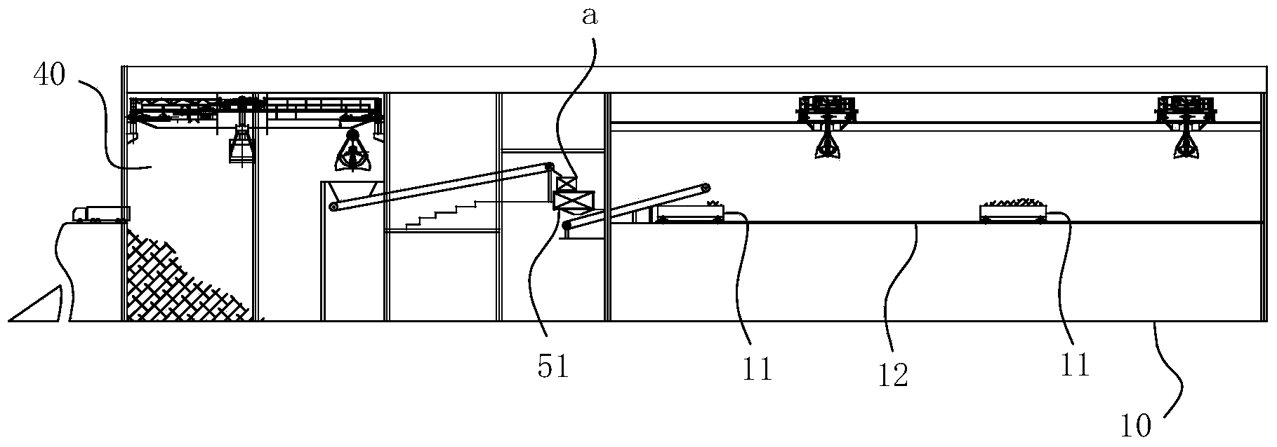
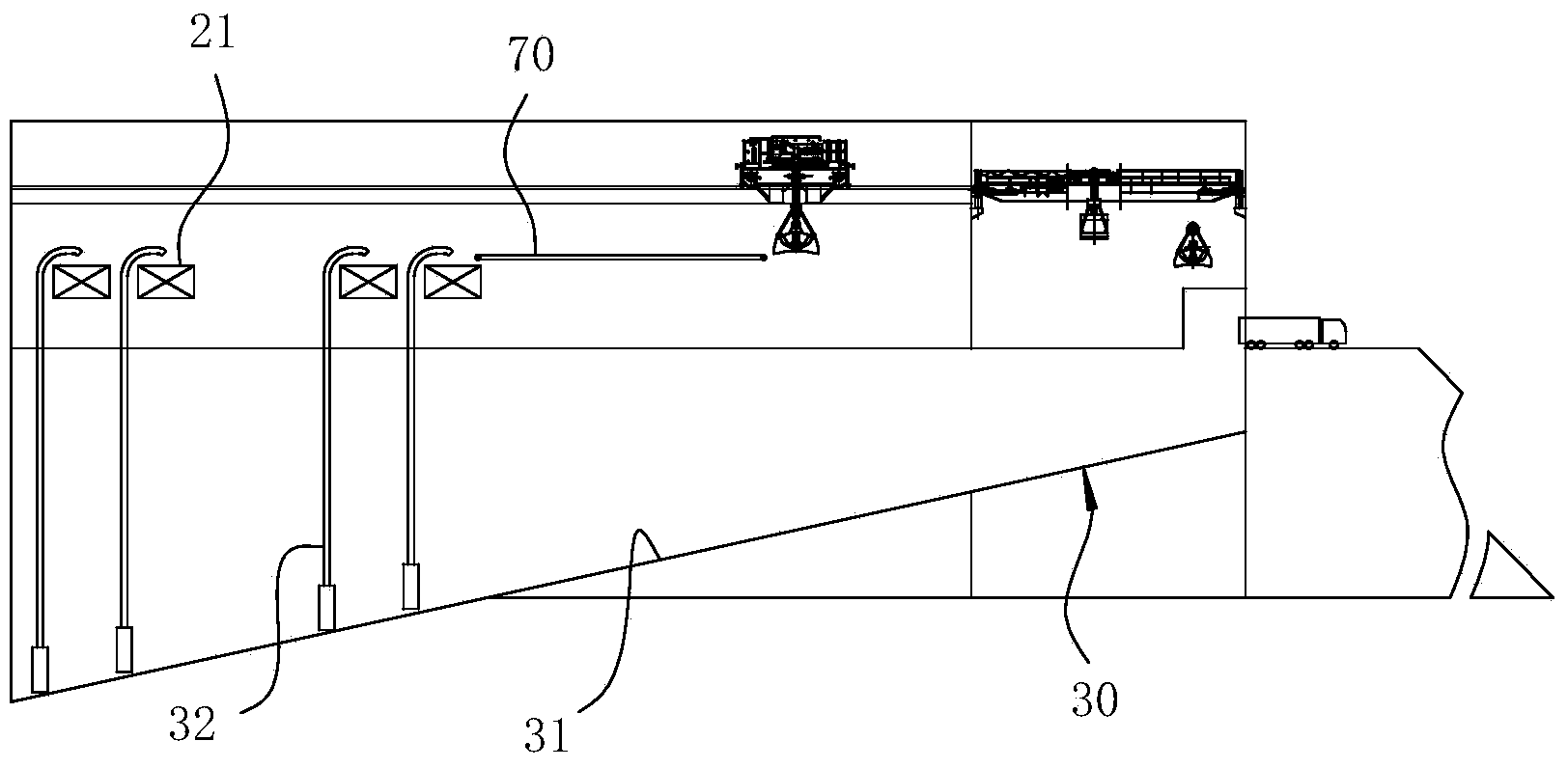
[0044] For ease of understanding, combined here Figure 1-9 Concretely set forth the specific implementation structure and workflow of the present invention:

[0045] Concrete structure of the present invention, as Figure 1-4 As shown, it includes a temporary domestic waste storage 40, a garbage conveying unit 50, and a garbage stacking unit 10 arranged end to end in sequence, wherein a temporary storage for food waste 60 is arranged side by side with the temporary storage for domestic waste 40, and a temporary storage for kitchen waste 60 The discharge end of the discharge end is erected at the garbage conveying unit 50 to ensure that the garbage in the temporary food waste storage 60 and the domestic garbage temporary storage 40 can be simultaneously discharged to the garbage conveying unit 50 and stirred to form mixed garbage. In addition, on the other side of the temporary kitchen waste storage 60 on the domestic waste temporary storage 40, the sludge storage and treatme...


PUM


Abstract

The invention belongs to the field of municipal solid waste disposal and particularly relates to mixed waste disposal system. The mixed waste disposal system at least comprises a waste pile-up unit used for waste pile-up fermentation and a waste incineration unit used for waste incineration. The mixed waste disposal system further comprises a sludge storage disposal pool, a material sliding ramp used for conveying materials is arranged in the sludge storage disposal pool, and the material sliding ramp is in the shape of an inclined face or a step-shaped structure becoming lower gradually. A sludge feeding end is arranged at the higher end of the material sliding ramp, and the lower end of the material sliding ramp forms a sludge discharging end. The time for sludge to flow from the sludge feeding end to the sludge discharging end along the material sliding ramp is longer than or equal to the number of days for the sludge to undergo set pile-up and warm-up fermentation and aerobic reaction. Both the waste pile-up unit and the discharging end of the sludge storage disposal pool are communicated with the feeding end of the waste incineration unit. Due to the simple and practical structure, mixed incineration disposal effect on municipal sludge and household waste can be achieved efficiently.

Description

technical field [0001] The invention belongs to the field of urban domestic garbage treatment, and in particular relates to a mixed garbage treatment system based on the classified treatment of urban garbage. Background technique [0002] Garbage incineration is a municipal garbage treatment method widely used in countries all over the world. Due to the requirement of energy recovery, it is gradually becoming the mainstream of incineration treatment. Practical experience shows that in the process of garbage incineration, the heat released by it should be sufficient to provide the heat required for the garbage to reach the combustion temperature and the activation energy required for the combustion reaction to occur, otherwise auxiliary fuel must be added to artificially increase the energy produced by its combustion. However, most of the existing waste incineration uses direct unloading and stacking, and then immediately enters the waste incinerator for incineration. There a...

Claims


Application Information

Patent Timeline
IPC IPC(8): F23G7/00F23G5/44B09B3/00C02F11/00C02F11/04B65G35/00B65G47/38
Inventor 李登平韩莹
Owner 南京溧水石湫机场科技工业园开发有限公司
Why Eureka
Try Eureka