Hydraulic linkage hydraulic counterblow hammer
A technology of hydraulic linkage and counter-hammer, applied in the field of hydraulic counter-hammer, can solve the problems of short service life of steel belt or wire rope, failure to meet use requirements, short service life of hammer head, etc., so as to reduce the number of maintenance and prolong the use. time, the effect of prolonging the service life
- Summary
- Abstract
- Description
- Claims
- Application Information
AI Technical Summary
Problems solved by technology
Method used
Image

Examples
Embodiment Construction
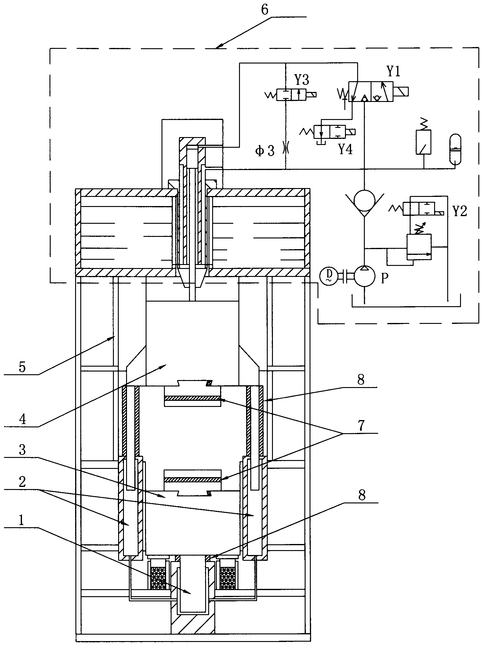
[0010] see figure 1 , the specific embodiment adopts the following technical scheme: it includes hydraulic linkage oil cylinder 1, hydraulic double linkage oil cylinder 2, lower hammer head 3, upper hammer head 4, hammer frame 5, hydraulic power and hydraulic control system 6, lower hammer head 3, The upper hammer head 4 is installed in the hammer frame 5, the linkage between the lower hammer head 3 and the upper hammer head 4 adopts a full hydraulic power drive system, and the movement is guided by the hammer frame 5, and the hydraulic linkage oil cylinder 1 and the hydraulic double linkage oil cylinder 2 are respectively installed On the base of the hammer frame 5, the hydraulic power and hydraulic control system 6 is installed on the top of the hammer frame 5, which also includes an anti-pressure device 7 and a protective cover 8, and the anti-pressure device 7 is respectively arranged in the lower hammer head 3 and the upper hammer head 4 , the protective cover 8 is respec...
PUM
 Abstract
Description
Claims
Application Information