Yellow phosphorus spiral pipe type gasifying combustion furnace

A combustion furnace and yellow phosphorus tube technology, which is applied in the direction of phosphorus oxides, phosphoric acid, phosphorus oxyacids, etc., can solve the problems of increasing investment in equipment funds, increasing energy consumption, and high requirements for transportation safety performance, achieving good economy Benefits and social benefits, the effect of quality assurance

Active Publication Date: 2014-05-07
GUANGXI MINGLI CHEM
View PDF3 Cites 3 Cited by
  • Summary
  • Abstract
  • Description
  • Claims
  • Application Information

AI Technical Summary

Problems solved by technology

The advantage of this method is that the molten phosphorus is fully burned after being sprayed; but its disadvantages are: due to the use of power machinery for transportation, firstly, the investment in equipment capital is increased; secondly, energy consumption is increased; thirdly, the safety performance of transportation is required to be high
In this method, although the yellow phosphorus enters the combustion furnace by high-pressure injection, the dispersibility is good, but the yellow phosphorus entering the combustion furnace is still in the form of droplets, and it is difficult to reach a state of full contact with the air, which affects to a certain extent. Burning effect of yellow phosphorus
In view of this, we have researched and invented a spiral tube yellow phosphorus gasification combustion furnace based on the actual production of phosphoric acid for many years. After checking the literature, the spiral tube yellow phosphorus gasification combustion furnace has not been used.

Method used


Image

  • Yellow phosphorus spiral pipe type gasifying combustion furnace
  • Yellow phosphorus spiral pipe type gasifying combustion furnace

Examples


Embodiment 1

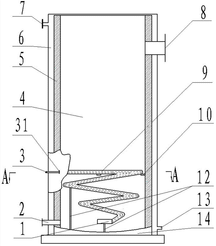
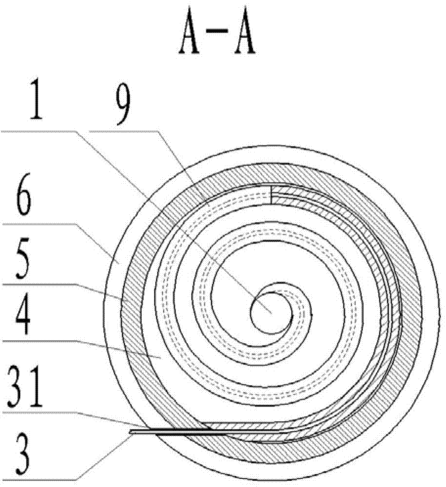
[0019] A spiral tube yellow phosphorus gasification combustion furnace includes a combustion furnace 4 connected to a phosphorus melting tank, and the combustion furnace 4 is provided with a spiral gasification tube 3 , a supporting hook 10 and a support frame 11 . The gasification pipe 3 spirals downward around the furnace center in the combustion furnace 4. The tail end of the gasification pipe 3 is placed in the middle of the bottom of the combustion furnace 4. The gasification pipe 3 is fixed on the bracket 10 on the inner wall of the combustion furnace 4. and the supporting frame 11, and the nozzle 1 is arranged at the tail end of the gasification pipe 3, and the nozzle 1 is arranged upward. The other end of the high-temperature graphite layer 9 is connected to the phosphorus melting tank through the sleeve pipe 31 provided by the furnace jacket 6 of the combustion furnace 4 .


PUM


Abstract

The invention discloses a yellow phosphorus spiral pipe type gasifying combustion furnace. The yellow phosphorus spiral pipe type gasifying combustion furnace comprises a combustion furnace, wherein the combustion furnace is connected with a molten phosphorus tank. The yellow phosphorus spiral pipe type gasifying combustion furnace is characterized in that a gasification pipe is arranged in the combustion furnace and is spirally arranged around the inner side of the combustion furnace, the tail end of the gasification pipe is arranged in the middle of the bottom of the combustion furnace and is provided with a nozzle, the other end of the gasification pipe is arranged outside the combustion furnace to be connected with the molten phosphorus tank, and the gasification pipe is fixedly arranged on a support hook of the inner wall of the combustion furnace and a support frame of a furnace chassis. According to the yellow phosphorus spiral pipe type gasifying combustion furnace, heat generated by combustion of yellow phosphorus is utilized to gasify liquid yellow phosphorus in the gasification pipe in the combustion furnace and enable the gasified yellow phosphorus to enter the combustion furnace to be fully mixed with air, thereby achieving complete combustion; the yellow phosphorus spiral pipe type gasifying combustion furnace is easy to operate, improves the phosphorus utilization rate while utilizing heat generated by phosphorus combustion, is suitable for large-scale industrial production and has good economic benefit, and the produced product has stable quality.

Description

technical field [0001] The invention belongs to the technical field of inorganic chemical industry and relates to a helical tube yellow phosphorus gasification combustion furnace. Background technique [0002] Phosphoric acid is an important part of the chemical industry and an important basic chemical raw material. The production methods of phosphoric acid are divided into thermal phosphoric acid and wet phosphoric acid. Thermal phosphoric acid refers to phosphoric acid that uses phosphate rock as raw material, firstly processes it into elemental phosphorus, and then processes it with elemental phosphorus; wet-process phosphoric acid refers to phosphoric acid that is directly processed from phosphate rock and inorganic acid as raw materials. The crude product of wet-process phosphoric acid contains more impurities and is mainly used to produce fertilizers; while thermal phosphoric acid has the advantages of high product concentration and less impurities, it can be used to ...

Claims


Application Information

Patent Timeline
Patent Type & Authority Applications(China)
IPC IPC(8): C01B25/20C01B25/12
Inventor 林军吴小海徐绍学黄新兴
Owner GUANGXI MINGLI CHEM
Why Eureka
Try Eureka