Rotary compressor and refrigerating circulating system with same
A technology of rotary compressors and compression chambers, applied in the direction of rotary piston machines, compressors, rotary piston pumps, etc., can solve the problem of high operating pressure, achieve the effects of preventing overcompression, improving exhaust efficiency, and small differences
- Summary
- Abstract
- Description
- Claims
- Application Information
AI Technical Summary
Problems solved by technology
Method used
Image
Examples
Embodiment 1
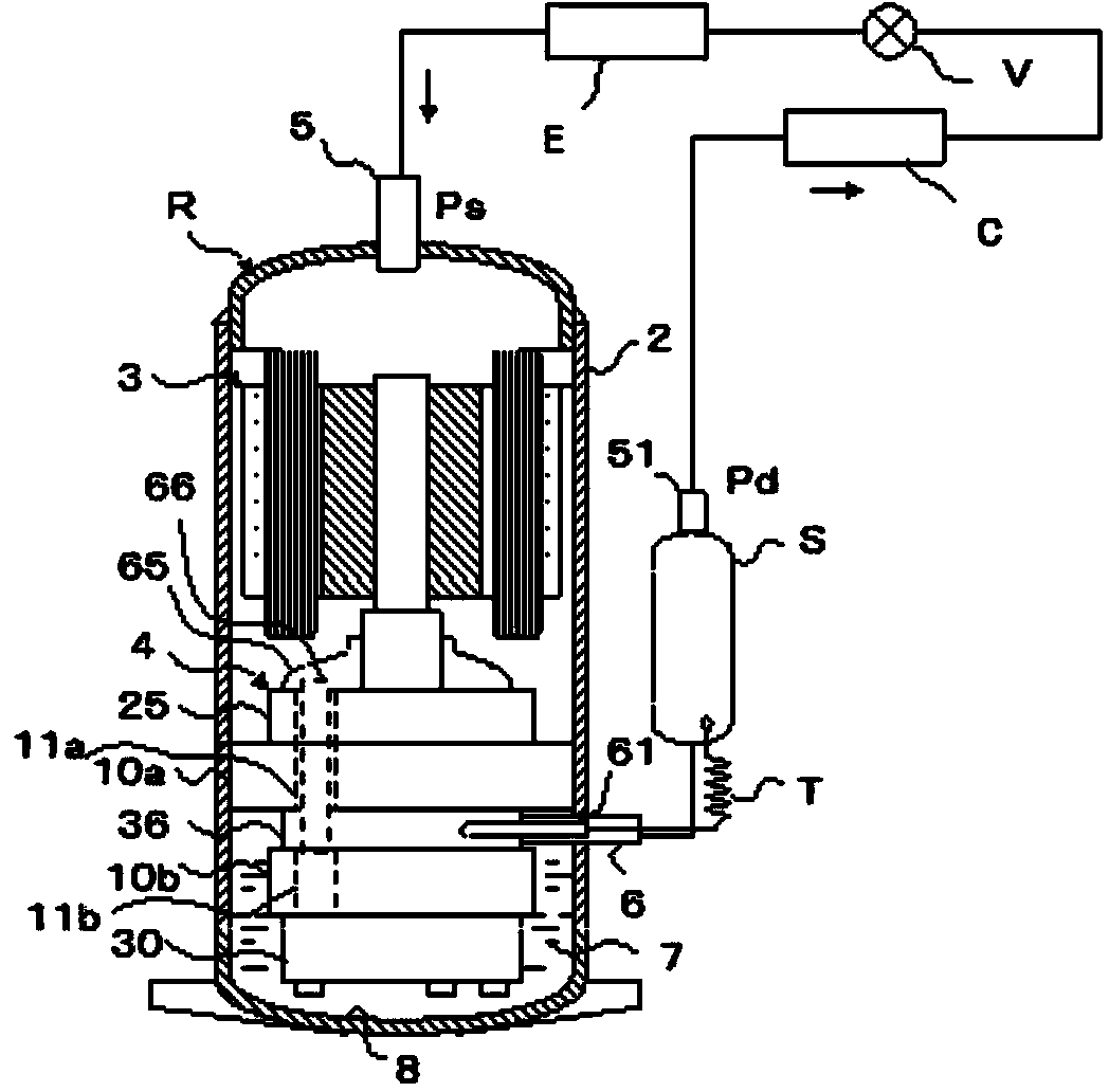
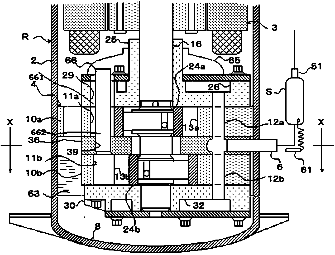
[0065] The shell low-pressure double-cylinder rotary compressor R of embodiment 1 and the refrigerating cycle system such as figure 1 shown. The rotary compressor R is composed of a compression device 4 attached to the inner diameter of the hermetic casing 2, and an electric motor 3 arranged above it. The compression device 4 is composed of a cylinder 10a fixed on the inner diameter of the housing, a middle partition 36 arranged thereunder, a cylinder 10b, a main bearing 25 and an auxiliary bearing 30, etc., and the above components are assembled by screws.
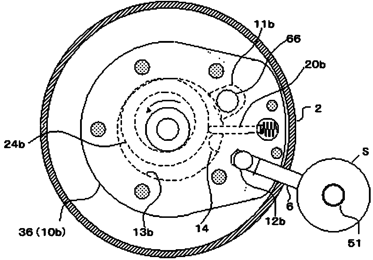
[0066] The exhaust pipe 6 and the oil injection pipe 61 connected at the outer periphery of the intermediate partition 36 are connected with the oil separator S together. Between the oil injection pipe 61 and the oil separator S, a capillary tube T for adjusting the amount of oil supplied to the compression chamber is provided. In addition, an air intake pipe 5 is arranged at the upper end of the housing 2 , and oil 7 i...
Embodiment 2
[0080] Figure 4 with representation Figure 4 Y~Y section of Figure 5 , which shows the lubrication design of the two compression chambers equipped on the compression device 4 . Since the internal pressure of the shell of the high-pressure rotary compressor is the high-pressure side, the oil in the oil pool will automatically lubricate the sliding parts (slides and pistons) and the inside of the compression chamber due to the pressure difference with the compression chamber to prevent the wear of the sliding parts resulting in inefficient compression. However, since the casing pressure of the low-pressure rotary compressor is on the low-pressure side, oil is forcibly supplied to the parts that slide in the compression chamber.
[0081] Figure 4 and Figure 5 As shown, the first oil supply pipe 61 and the second oil supply pipe 71 provided on the intermediate partition 36 are oil supply means for the two compression chambers. Since the first oil supply pipe 61 is opene...
Embodiment 2
[0086] Here, if the oil separation efficiency of the oil separator S is n, nx8% is the amount of oil separated and guaranteed in the oil separator S. If (1-n)x8% cannot be secured, it will become the discharge of the refrigerant circulation system. Oil volume (OCR). Usually, the upper limit of OCR is 1%. In Embodiment 2, if the OCR is 1%, it is consistent with the total oil supply (2g=1%) of the two compression chambers of the second oil supply pipe 71 .
[0087] That is to say, the above-mentioned oil volume control method is related to 2g=OCR. If the efficiency (n) of the oil separator S deteriorates, the oil discharge volume (OCR) will increase, and it is also necessary to increase the delivery from the oil supply pipe to the compression chamber. the necessary fuel supply. Therefore, the oil circulation control method of Embodiment 2 is established. In addition, if the oil separation efficiency (n) is known, the oil supply quantity related to the oil supply pipe 61 and th...
PUM
 Abstract
Description
Claims
Application Information
 - R&D
- Intellectual Property
- Life Sciences
- Materials
- Tech Scout
- Unparalleled Data Quality
- Higher Quality Content
- 60% Fewer Hallucinations
Browse by: Latest US Patents, China's latest patents, Technical Efficacy Thesaurus, Application Domain, Technology Topic, Popular Technical Reports.
© 2025 PatSnap. All rights reserved.Legal|Privacy policy|Modern Slavery Act Transparency Statement|Sitemap|About US| Contact US: help@patsnap.com


