High-temperature-resistance optical fiber

A high-temperature, fiber-optic technology, applied in cladding fibers, optical waveguides and light guides, etc., can solve the problems of poor fiber performance, difficulty, and reliability degradation, and achieve the effect of superior temperature performance and good attenuation

Active Publication Date: 2014-05-07
FENGHUO COMM SCI & TECH CO LTD
View PDF5 Cites 16 Cited by
  • Summary
  • Abstract
  • Description
  • Claims
  • Application Information

AI Technical Summary

Problems solved by technology

[0003] However, when the use environment is relatively special or relatively harsh, this double-coating structure design has the phenomenon of reduced reliability, poor optical fiber performance, or even unusable
In some applications, such as high-temperature environments such as oil well exploration, optical fibers have also been used for signal transmission, but the maximum temperature that conventional coatings can adapt to is 85°C. If metal coatings are used for direct coating, on the one hand, the attenuation and other performance of optical fibers will be reduced. It is greatly affected, and the coating layer is also difficult to peel off, making it difficult to use

Method used


Image

  • High-temperature-resistance optical fiber

Examples


Embodiment 1

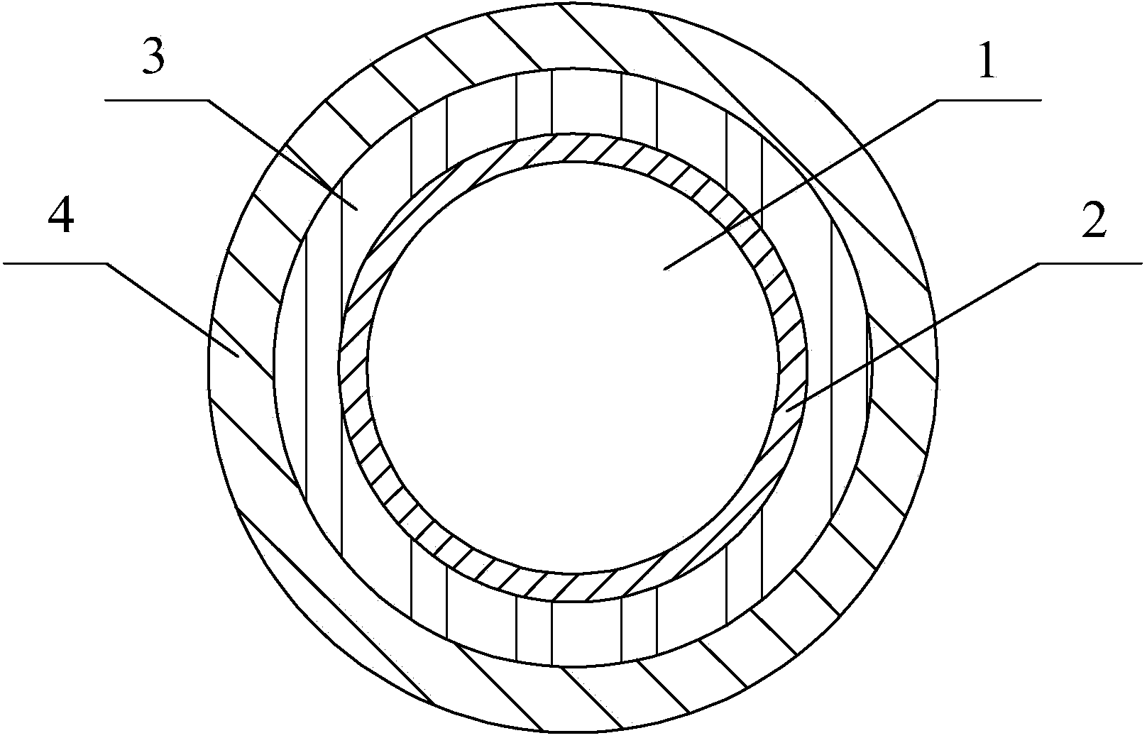
[0021] The first coating 2 is carbon with a thickness of 3 nm; the second coating 3 is polyimide with a Young's modulus of 0.8 GPa, and the thickness is 20 μm to 35 μm; the third coating 4 is a Young's modulus of 3.5 The polyimide of GPa, the thickness is 25μm~45μm.

[0022] The method for forming the high-temperature-resistant optical fiber in this embodiment is as follows: firstly, the quartz rod is melted and drawn into the optical fiber body 1 by using a high-temperature furnace, and a 3nm-thick fiber is deposited on its surface through a plasma chemical vapor deposition device arranged next to the lower furnace mouth of the high-temperature furnace. The carbon layer is the first coating 2 . Two more coats are then applied using the dry+wet method, first applying the second coat 3 by seal pressure coating, which is cured from liquid to solid using UV light; then applied again by seal pressure coating The third coating 4 is also cured from liquid to solid by using ultravio...

Embodiment 2

[0025] The first coating 2 is a polyacrylic resin with a Young's modulus of 1.2 MPa, and its thickness is 20 μm to 30 μm; the second coating 3 is a high temperature resistant polyacrylic resin with a Young's modulus of 1100 MPa, and its thickness is 20 μm to 35 μm; Coating 4 is polyimide with a Young's modulus of 4.0 GPa and a thickness of 10 μm to 30 μm.

[0026] The method for forming the high-temperature-resistant optical fiber in this embodiment is as follows: first, the quartz rod is fused and drawn into the optical fiber body 1 by using a high-temperature furnace, and the optical fiber diameter is 125 microns, and then the first coating 2 and the second coating 3 are applied by a wet-wet method. The first coating 2 and the second coating 3 are coated together by the sealing pressure coating method, and then the two coatings are cured from liquid to solid together with ultraviolet light, and the polyacrylic resin with Young's modulus of 1.2MPa is the first The first coati...


PUM

PropertyMeasurementUnit
thicknessaaaaaaaaaa
thicknessaaaaaaaaaa
thicknessaaaaaaaaaa

Abstract

Disclosed is a high-temperature-resistance optical fiber which relates to the field of optical-fiber manufacturing. The optical fiber includes an optical-fiber body and coatings which cover the optical-fiber body. The optical-fiber body is covered with three coatings from inside to outside. A third coating at the outermost layer is a polyimide with a Young modulus higher than 3GPa. When a first coating is carbon, a second coating is a polyimide with a Young modulus lower than 1GPa. When the first coating is a polyacrylic resin with a Young modulus lower than 1.5MPa, the second coating is a high-temperature-resistance polyacrylic resin with a Young modulus higher than 1GPa. Compared with conventional double-coating optical fibers, the high-temperature-resistance optical fiber has transmission characteristics of better temperature performance and better attenuation and the like under a high-temperature environment so that global properties of the optical fiber meet demands of a high-temperature environment and the optical fiber is capable of standing a temperature up to 350 DEG C.

Description

technical field [0001] The invention relates to the field of optical fiber manufacturing, in particular to a high temperature resistant optical fiber. Background technique [0002] At present, the coating structure of conventional optical fibers is generally a double-coating structure, that is, it is divided into an inner coating next to the silica fiber and an outer coating wrapped around the inner coating. Generally, the inner coating is made of a softer material, and the outer coating The layer is a harder material. When the optical fiber is subjected to external force, the harder outer layer first acts to resist the external force, and then the softer inner layer buffers the external force. Now the optical fiber coating materials used in mainstream optical fibers are all polyacrylic resins. The difference between the inner coating and the outer coating is only a part of the composition. The advantage of this is that the inner coating material and the outer coating mater...

Claims


Application Information

Patent Timeline
Patent Type & Authority Applications(China)
IPC IPC(8): G02B6/02
Inventor 罗文勇李诗愈陈伟柯一礼杜城张涛莫琦胡福明
Owner FENGHUO COMM SCI & TECH CO LTD
Why Eureka
Try Eureka