Solid Electrolytic Capacitor

A solid electrolysis, solid electrolyte technology, applied in solid electrolytic capacitors, electrolytic capacitors, capacitors and other directions, can solve the problems of labor-hours, large thickness space, long time, etc., to shorten the lead-out path, eliminate the bending step difference, electrostatic capacitance value added effect

Active Publication Date: 2017-03-01
NICHICON CAPACITOR LTD
View PDF12 Cites 0 Cited by
  • Summary
  • Abstract
  • Description
  • Claims
  • Application Information

AI Technical Summary

Problems solved by technology

However, there is the following problem, that is, in order to shape the cylindrical winding element, the diameter of the winding element is restricted, and after packaging, it still occupies a relatively large thickness space, and it is difficult to further meet the narrow plate requirements
Moreover, as a second problem, although there are chip-type solid electrolytic capacitors with a laminated structure that can form elements thinner, when polypyrrole is formed as a solid electrolyte layer, a chemically polymerized film is formed on the first layer. In addition, the method of electrolytically polymerizing the second layer takes a long time for electrolytic polymerization, and furthermore, the electrolytic polymerization must be performed on a single layer and welded according to the number of laminated sheets, so there is a problem that it takes man-hours

Method used


Image

  • Solid Electrolytic Capacitor
  • Solid Electrolytic Capacitor
  • Solid Electrolytic Capacitor

Examples


no. 1 approach

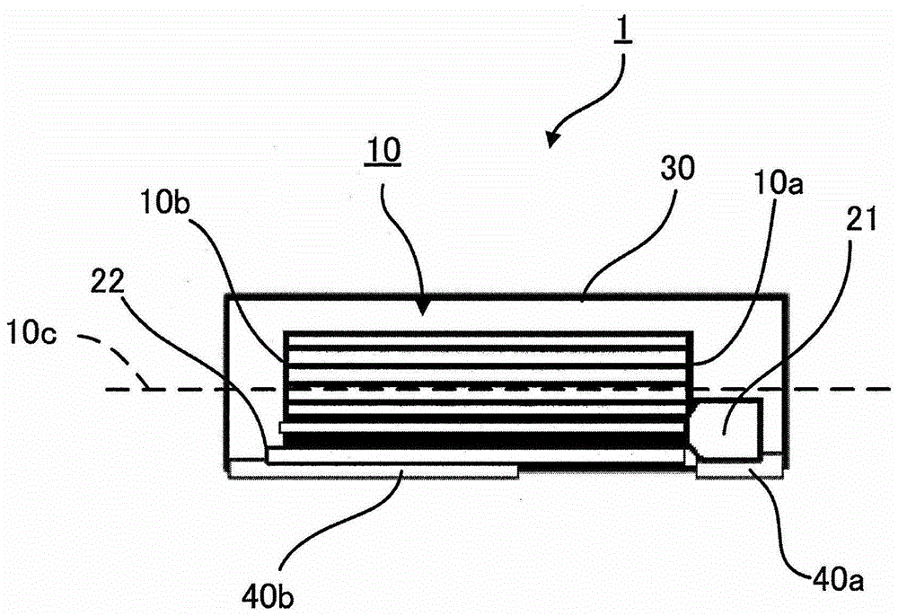
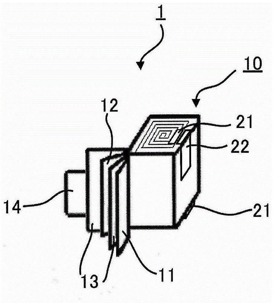
[0056] figure 1 It is a schematic longitudinal sectional view schematically showing the solid electrolytic capacitor according to the first embodiment of the present invention. figure 2 It is a schematic perspective view schematically showing the disassembled structure of the solid electrolytic capacitor of the first embodiment before the solid electrolyte is formed.

[0057] Such as figure 2 As shown, the solid electrolytic capacitor 1 includes: a rectangular parallelepiped element 10, the coiled element formed by winding the anode foil 11, the cathode foil 12, and the separator 13 arranged between the anode foil 11 and the cathode foil 12 is in the shape of a flat cuboid , form a solid electrolyte; anode lead-out terminal 21 is connected to anode foil 11; cathode lead-out terminal 22 is connected to cathode foil 12; figure 1 ).

[0058] exist figure 2 In , the end of the anti-roll tape 14 is free, but in fact, the end of the anti-roll tape 14 is pasted on the side o...

no. 2 approach

[0115] Hereinafter, the same components as those of the solid electrolytic capacitor 1 according to the first embodiment will be described with the same reference numerals. In addition, the description in the first embodiment is also applicable to the part in the second embodiment, and the description thereof will be omitted.

[0116] use Figure 13 to Figure 16 A second embodiment will be described.

[0117] Figure 13 is a schematic longitudinal sectional view schematically showing a solid electrolytic capacitor according to the second embodiment.

[0118] Such as Figure 13 As shown, also in the second embodiment, the cathode lead-out terminal 22 is arranged at the outermost shell of the rectangular parallelepiped element 10 similarly to the first embodiment. That is, the cathode lead-out terminal 22 is on the side of the cuboid element 10 (the bottom surface of the cuboid element 10, Figure 13 bottom face) exposed. And, the exposed cathode lead-out terminal 22 is co...

Embodiment 1

[0135] As Example 1, the solid electrolytic capacitor 1 (6.3 V, 100 μF) shown in the first embodiment was produced ( figure 1 ). The size of the packaging box of the solid electrolytic capacitor 1 is 7.3mm×4.3mm×2.8mm. As the lead frames 40 ( 40 a and 40 b ), a copper frame material whose surface was nickel-plated and whose thickness was 100 μm was used. In addition, at the time of manufacture, before the lead frame 40a is connected to the anode lead-out terminal 21 (aluminum anode tab), a needle is inserted through the connection position of the lead frame 40a to the anode lead-out terminal 21, thereby, at the connection position The protruding portion 41 is formed. Use a quadrangular pyramid-shaped front end of needles as needles. The lead frame 40a and the anode lead-out terminal 21 are connected by an inverter resistance welding machine. Then, before the lead frame 40b is connected to the cathode lead-out terminal 22 (nickel-plated copper base material cathode tab),...


PUM


Abstract

An object of the present invention is to provide a solid electrolytic capacitor that can eliminate the complexity of manufacturing steps and can increase the electrostatic capacitance. The present invention is a solid electrolytic capacitor. The solid electrolytic capacitor includes a rectangular parallelepiped element, and the winding element formed by winding an anode foil, a cathode foil, and a separator between the anode foil and the cathode foil is a flat rectangular parallelepiped. an anode lead-out terminal, which is connected to the anode foil; a cathode lead-out terminal, which is connected to the cathode foil; and a packaging body, which packs the rectangular parallelepiped element; The two are arranged on one side relative to the winding core of the rectangular parallelepiped element, and the cathode lead-out terminal is arranged at the outermost shell of the rectangular parallelepiped element.

Description

technical field [0001] The present invention relates to a solid electrolytic capacitor. Background technique [0002] In recent years, with the high performance and miniaturization of electronic equipment, molded chip parts that take into account the mounting density of parts have become mainstream. Aluminum electrolytic capacitors are no exception, and surface-mounted (Surfaced Mounting Technology, SMT) aluminum electrolytic capacitors are also widely used. [0003] Surface mount technology is a new generation of electronic assembly technology, which compresses traditional electronic parts into a few tenths of the previous volume, and realizes high density, high reliability, miniaturization, low cost and automatic production of electronic parts. However, for aluminum electrolytic capacitors, common surface mount products are vertical type (commonly known as V chip), but there is a limit in electronic equipment that requires a narrow board. [0004] As a technique capable ...

Claims


Application Information

Patent Timeline
Patent Type & Authority Patents(China)
IPC IPC(8): H01G9/012H01G9/15
CPCH01G9/02H01G9/025H01G9/055H01G9/151
Inventor 土屋昌义石塚英俊汤成戎
Owner NICHICON CAPACITOR LTD
Why Eureka
Try Eureka