
Laser drilling device used for machining hard and brittle substrate

A laser drilling and substrate technology, which is applied in laser welding equipment, metal processing equipment, manufacturing tools, etc., can solve problems such as cracks in the hole wall of alumina ceramic substrates, precision instruments, adverse environmental effects, and laser drilling track deviation. , to achieve the effect of small single pulse energy, avoid a large amount of dust, and avoid offset

Inactive Publication Date: 2014-05-14
INNO LASER TECH CORP LTD +1
View PDF5 Cites 6 Cited by
  • Summary
  • Abstract
  • Description
  • Claims
  • Application Information

AI Technical Summary

Problems solved by technology

[0004] Based on the above points, it can be seen that the existing laser drilling equipment needs to have the two conditions of high laser peak power and coating PVA on the surface of the alumina ceramic substrate. In the past, PVA was required to be coated, resulting in complicated processing procedures and low processing efficiency. At the same time, the laser beam still has a high impact strength, so there is still a risk of cracks or even fragmentation of the alumina ceramic substrate, and the high impact The strength causes a large amount of dust to be generated at the punching point, which will have adverse effects on precision instruments and the environment
In addition, the existing laser drilling equipment uses motors to drive belts or gears to drive optical components such as prisms and mirrors. This type of driving mechanism will shake during work, which will cause the deviation of the laser drilling track and affect the processing accuracy. sex

Method used


Image

  • Laser drilling device used for machining hard and brittle substrate
  • Laser drilling device used for machining hard and brittle substrate

Examples


Embodiment Construction

[0013] The present invention will be described in more detail below in conjunction with the accompanying drawings and embodiments.

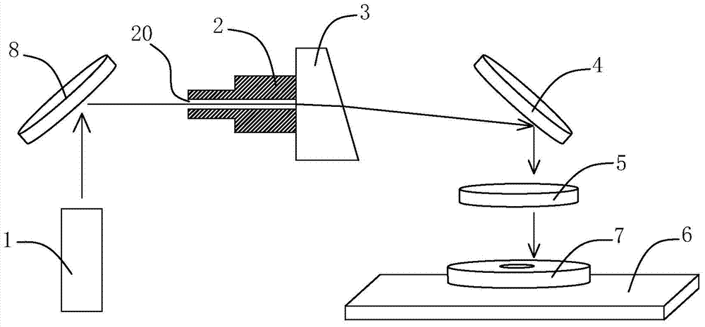
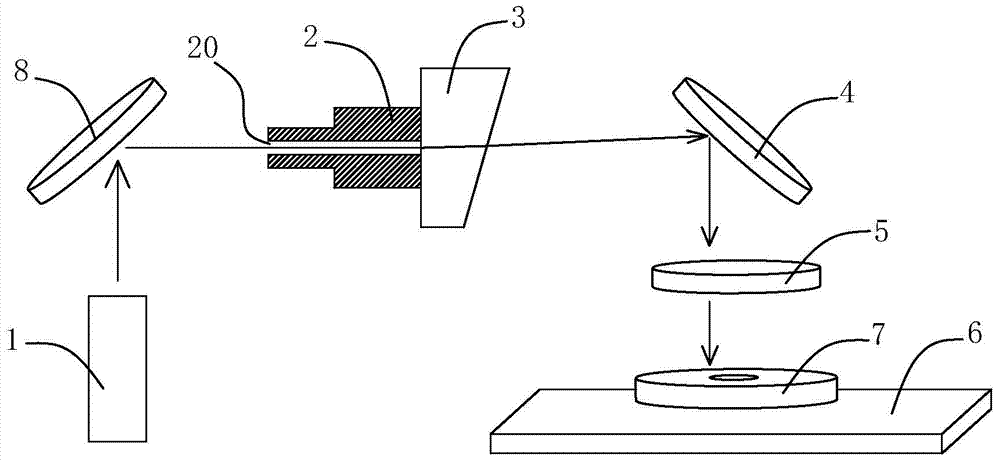
[0014] The invention discloses a laser drilling device for processing hard and brittle substrates, which combines figure 1 with figure 2 As shown, it includes a laser head 1, a drive device 2, a wedge prism 3, a first reflector 4, a focusing mirror 5 and a stage 6 are arranged in sequence along the transmission direction of the laser pulse emitted by the laser head 1, and a hard and brittle substrate 7 is placed on the stage 6, the laser head 1 is a Q-switched laser, that is, a Q-switched narrow pulse width, short-wavelength ultraviolet diode-pumped solid-state laser, the wedge prism 3 is fixedly connected to the driving device 2, and the wedge prism 3 The light emitting surface is an inclined surface, and the driving device 2 is provided with a light guide hole 20. Driven by the drive device 2, the wedge-angle prism 3 rotates around the axis o...


PUM

PropertyMeasurementUnit
angleaaaaaaaaaa

Abstract

The invention discloses a laser drilling device used for machining a hard and brittle substrate. According to the device, a laser head is a Q-switch laser device, a wedge prism is fixedly connected with a driving device, the light-emitting surface of the wedge prism is an oblique surface, a light guiding hole is formed in the driving device, the driving device rotates around the axis of the light guide hole, and laser pulses emitted by the laser head are transmitted to the wedge prism through the light guiding hole, pass through a first reflector and a focus lens in sequence after being refracted through the wedge prism, and then are transmitted to the hard and brittle substrate. According to the laser drilling device, the Q-switch laser device serves as a laser source, and breakage of the hard and brittle substrate caused by overhigh thermal stress is avoided; meanwhile, due to the fact that the hard and brittle substrate does not need to be coated with PVA, machining processes are simplified, and machining efficiency is improved; furthermore, the driving device provided with the light guiding hole drives the wedge prism to rotate to enable the rotation of the wedge prism to be more stable, deviation of a laser drilling track is avoided, and accurate machining is achieved.

Description

technical field [0001] The invention relates to drilling processing equipment, in particular to a laser drilling device for processing hard and brittle substrates. Background technique [0002] Laser drilling is the earliest practical laser processing technology, and it is also one of the main application fields of laser processing. With the rapid development of modern industry and science and technology, the market demand for hard and brittle substrate materials such as ceramics is increasing. Traditional drilling methods can no longer meet certain technological requirements. [0003] At present, the processing method of hard and brittle substrates is to use pulsed laser beams with a wavelength of 1.06um and more than 200 watts to drill holes on hard and brittle substrates. Taking alumina ceramic substrates as an example, due to the high requirements for the average power of the laser, it is usually used A carbon dioxide laser with an average power of more than 100 watts. ...

Claims


Application Information

Patent Timeline
Patent Type & Authority Applications(China)
IPC IPC(8): B23K26/382B23K26/064
CPCB23K26/0652B23K26/382
Inventor 陈强智
Owner INNO LASER TECH CORP LTD
Learn More