Multi-stage amplitude modulation visible optical signal coding method and apparatus and decoding method and apparatus, and system
An encoding method and visible light technology, applied in the field of visible light communication, can solve problems such as low transmission rate
- Summary
- Abstract
- Description
- Claims
- Application Information
AI Technical Summary
Problems solved by technology
Method used
Image

Examples
no. 1 example
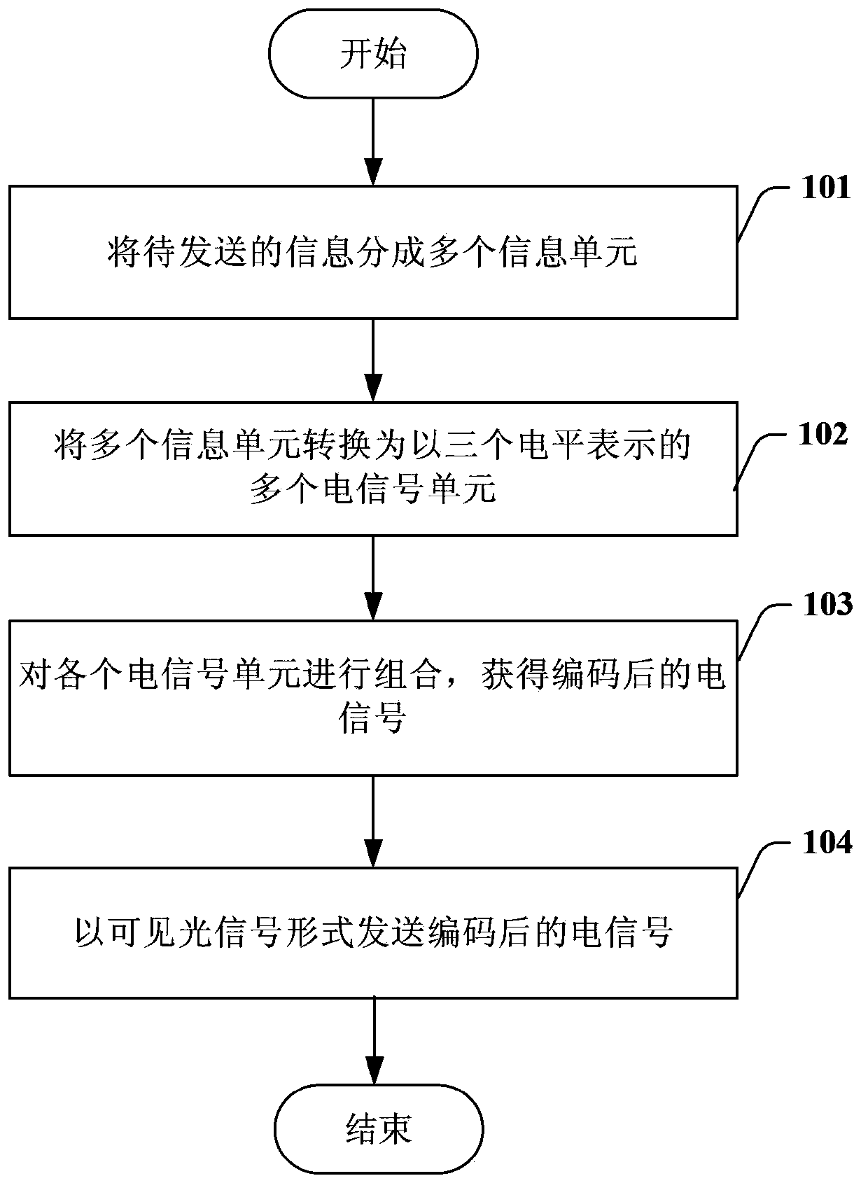
[0058] see figure 1 , is the encoding flowchart of the visible light signal in the first embodiment of the present invention, and the encoding process includes:
[0059] Step 101, divide the information to be sent into multiple information units.
[0060] Raw information can be represented by binary. Each information unit contains a plurality of bits (bit). For example, each information element contains 2 bits.
[0061] Step 102, convert the multiple information units into multiple electrical signal units.
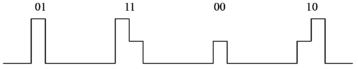
[0062] In this embodiment, these electrical signal units are represented by three levels, such as 0, 1V and 2V. Wherein, the first level, such as 0V, is set as the reference level, which is used to indicate the interval between adjacent electrical signal units. The other two levels, such as 1V and 2V, are used to combine with each other in the electrical signal unit to represent 2 bits. Specifically, in an electrical signal unit, when the level jumps from 0V to 1V, a...
no. 2 example
[0092] see Figure 4 , is the encoding flowchart of the visible light signal in the second embodiment of the present invention, and the encoding process includes:
[0093] Step 301, divide the information to be sent into multiple information units.
[0094] Raw information can be represented by binary. Each information unit contains a plurality of bits (bit). For example, each information element contains 4 bits.
[0095] Step 302, convert the multiple information units into multiple electrical signal units.
[0096] In this embodiment, these electrical signal units are represented by four levels, such as 0V, 1V, 2V and 3V. Wherein, the first level, such as 0V, is set as the reference level, which is used to indicate the interval between adjacent electrical signal units. The other three levels, such as 1V, 2V and 3V, are used to combine with each other in the electrical signal unit to represent 3 bits.
[0097] For example, in an electrical signal unit, when the level ju...
no. 3 example
[0127] This embodiment is implemented in a photonic access control system, where a portable electronic device such as a mobile phone can be used as a sending end, and the access control end can be used as a receiving end. In addition to decoding the signal, the access control terminal can further use the signal for matching to decide whether to open the door.
[0128] see Figure 7 , is the encoding flow chart of the visible light signal according to the third embodiment of the present invention, and the encoding process includes:
[0129] Step 701, divide the identity authentication information to be sent into multiple information units in the mobile phone.
[0130] The original identity authentication information can be represented by binary. Each information unit contains a plurality of bits (bit). For example, each information element contains 2 bits.
[0131] Step 702, converting the multiple information units into multiple electrical signal units represented by three...
PUM
 Abstract
Description
Claims
Application Information
 - R&D
- Intellectual Property
- Life Sciences
- Materials
- Tech Scout
- Unparalleled Data Quality
- Higher Quality Content
- 60% Fewer Hallucinations
Browse by: Latest US Patents, China's latest patents, Technical Efficacy Thesaurus, Application Domain, Technology Topic, Popular Technical Reports.
© 2025 PatSnap. All rights reserved.Legal|Privacy policy|Modern Slavery Act Transparency Statement|Sitemap|About US| Contact US: help@patsnap.com