High-speed mechanical arm with precise positioning function

A technology of precise positioning and manipulators, applied in the direction of manipulators, program-controlled manipulators, claw arms, etc., can solve the problems of limited structural length, low speed, low positioning accuracy, etc., and achieve the effect of large length range

Active Publication Date: 2014-05-21
FUJISAN IND TECH CO LTD OF SHENZHEN CITY
View PDF7 Cites 3 Cited by
  • Summary
  • Abstract
  • Description
  • Claims
  • Application Information

AI Technical Summary

Problems solved by technology

[0002] The mechanical arm is used in process automation, partially replacing manual operation, and can complete the transfer and loading and unloading of workpieces according to the requirements of the production process, following certain time and position rules, and can complete long-distance high-speed transportation, and requires accurate positioning and adjustable speed control. High degree, such as the delivery, positioning and assembly of parts in the assembly line of large machinery, the driving device of the high-speed camera installed on the side of the short runway of the stadium, are all applications of high-speed robotic arms. The robotic arms currently produced and used generally use rolling There are two transmission methods: nut-screw and synchronous belt. The rolling screw-nut kinematic pair is a commonly used transmission device for converting rotary motion into linear motion. The rolling screw nut transmission structure has high transmission efficiency, small frictional resistance and high transmission accuracy. From the point of view of the transmission principle of the mechanism, the rotational motion of the screw is converted into the linear motion of the nut. The speed of the mechanical arm installed on the nut depends on the lead and the rotation speed of the screw. The speed is relatively low, and the sliding range of the mechanism is the same as that of the screw. The length of the rod is related, and the length of the lead screw must be controlled within a certain range. If the length of the lead screw exceeds a certain limit, it will shake and cause the overall instability of the mechanism.
The existing nut-screw type manipulator has low speed, low positioning accuracy and limited structural length

Method used


Image

  • High-speed mechanical arm with precise positioning function
  • High-speed mechanical arm with precise positioning function
  • High-speed mechanical arm with precise positioning function

Examples


Embodiment 1

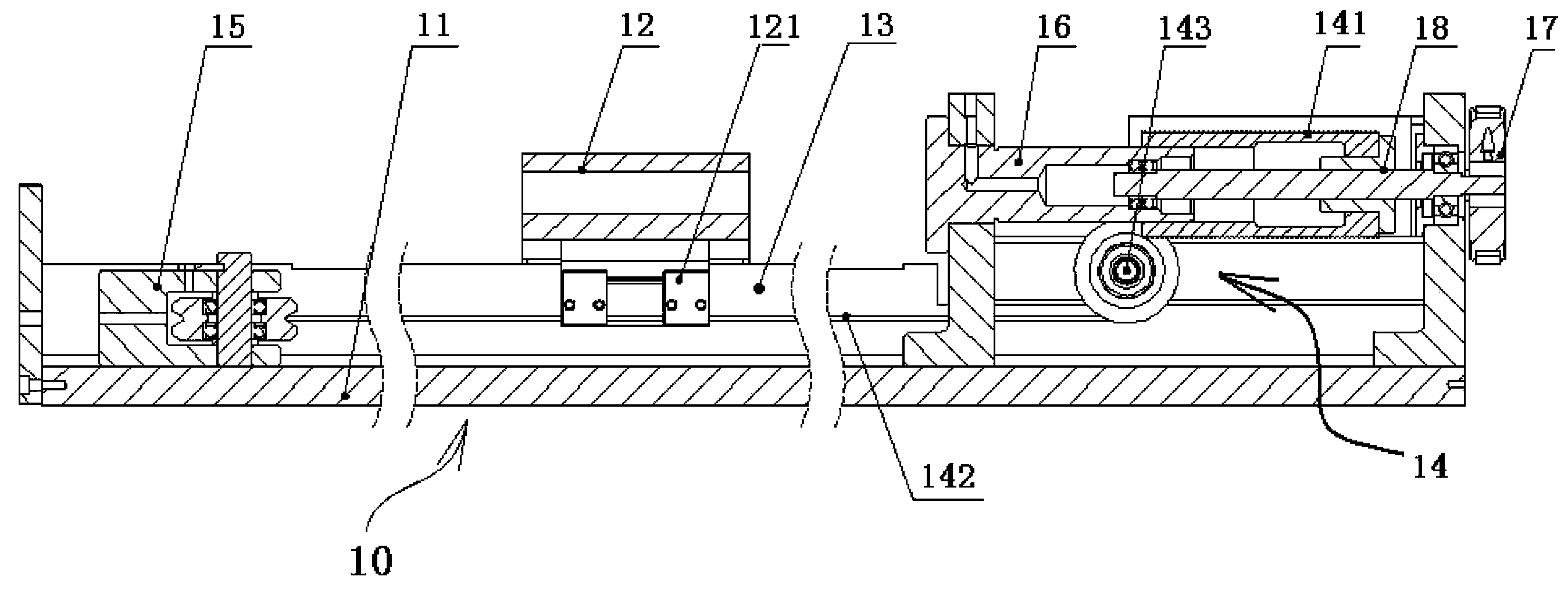
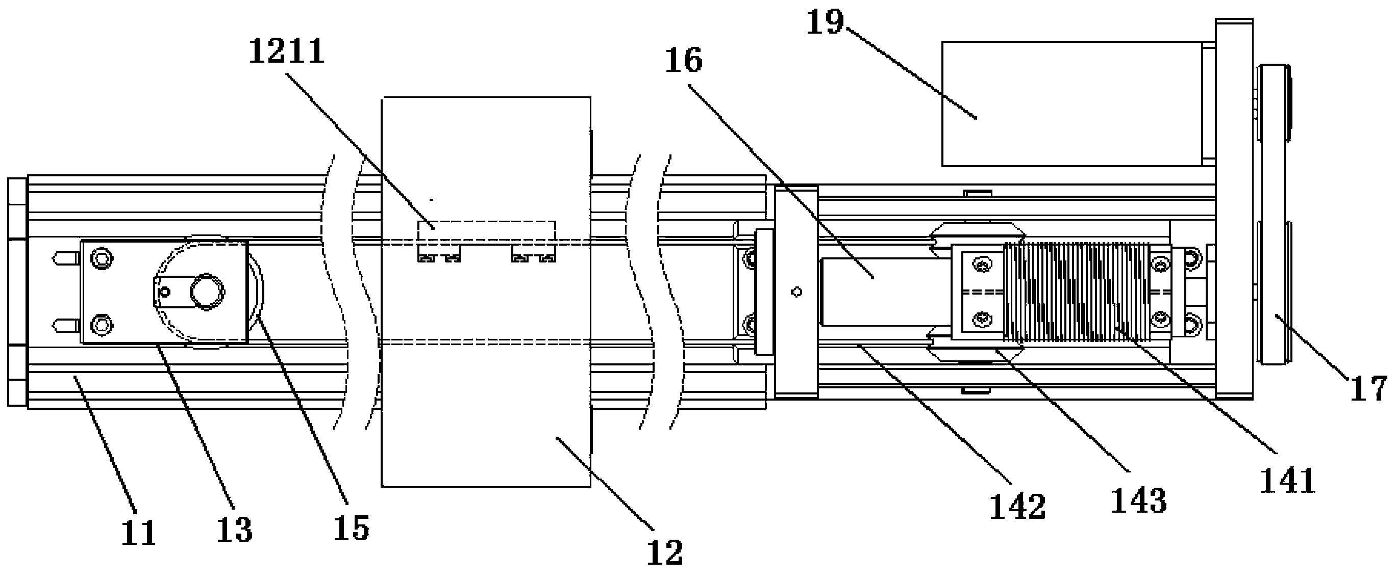
[0021] Please refer to figure 1 and figure 2 , the precise positioning high-speed mechanical arm 10 proposed in this embodiment includes a motor, a drive part 14, a frame 11 and a slider 12, and the frame 11 has a chute 13, and the slider 12 is installed on the chute 13 Inside, the driving part 14 drives the slider 12 to move along the chute 13, and the feature is that the driving part 14 includes a reel 141 and a steel cable 142 wound on the reel 141, and the reel 141 There is a thread groove 1411 on the top, and the steel cable 142 is coiled in the thread groove 1411. The steel cable 142 is installed between the reel 141 and the chute 13 to form a running circuit. The bottom of block 12 is fixed. Change the original rolling screw-nut motion pair structure and use the steel cable to directly drive the slider. The flexible feature of the steel cable 142 itself can be compatible with rotary motion and linear motion, and convert rotary motion into linear motion.

[0022] The...

Embodiment 2

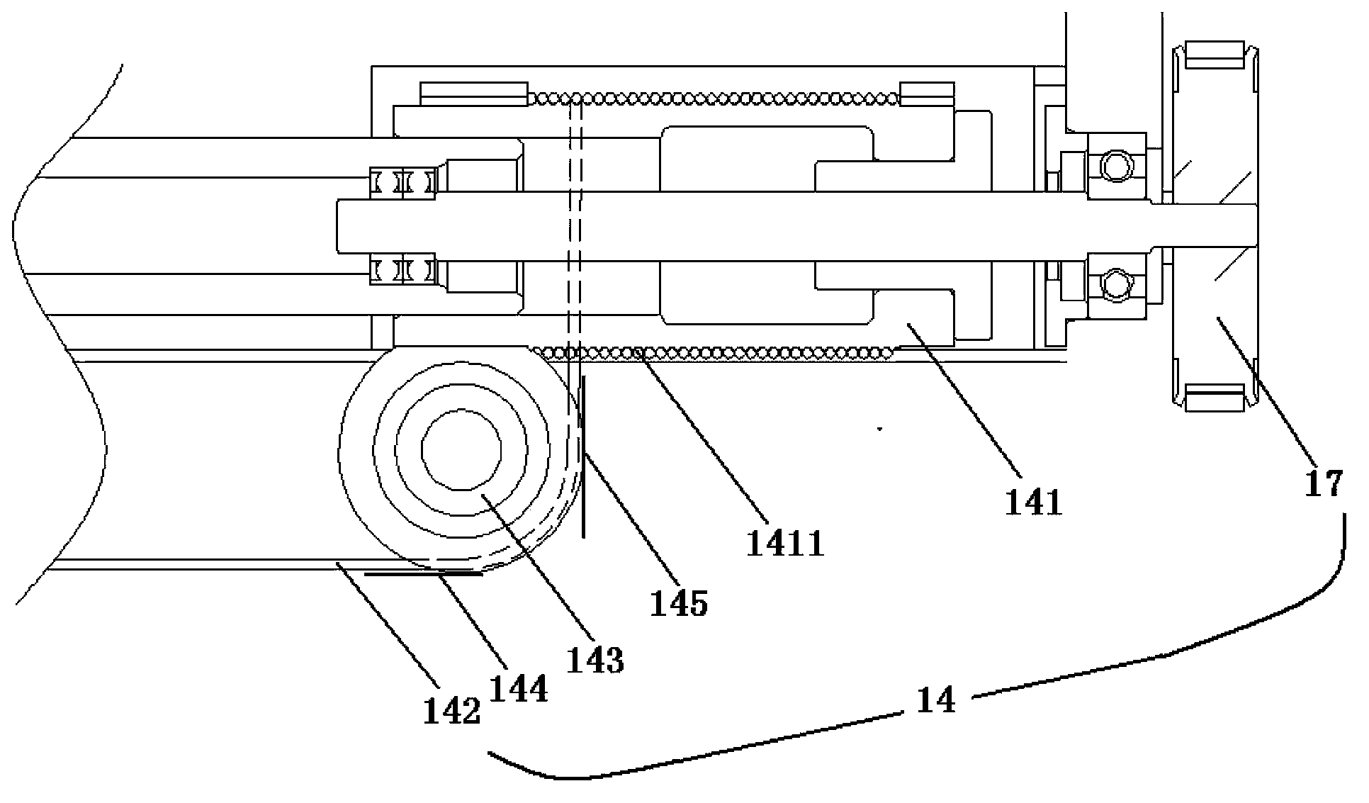
[0031] Please refer to image 3 , the basic mechanism structure of the high-speed mechanical arm 20 in this embodiment is the same as that of Embodiment 1, the difference is that the reel 241 is set in the drive part 24 in the manner of its axial vertical chute, then the steel cable 242 Directly wound on the thread groove 2411 of the reel 241, omitting the structure of the left and right guide wheels. In this embodiment, the reel is also installed on a fixed seat, and as the reel rotates, the reel itself moves on the fixed seat, there are external threads on the fixed seat and internal threads inside the reel, and the reel is sleeved on the fixed seat. On the fixed seat, the width of the thread groove on the fixed seat is consistent with the width of the thread groove of the reel itself, and the moving distance of the reel itself and the distance that the steel cable moves on the reel due to the rotation of the reel cancel each other out, maintaining the position of the steel ...


PUM


Abstract

A high-speed mechanical arm with a precise positioning function comprises a motor, a driving part, a rack and a sliding block, wherein a sliding slot is arranged on the rack, the sliding block is arranged in the sliding slot and is driven by the driving part to move along the sliding slot. The mechanical arm is characterized in that the driving part comprises a winding drum and a steel wire rope wound on the winding drum, a threaded groove is arranged on the winding drum, the steel wire rope is coiled in the threaded groove and is arranged between the winding drum and the sliding slot to form a revolving loop, and a section, which is arranged in the sliding slot, of the steel wire rope is fastened with the bottom of the sliding block. The winding drum with the threaded slot is driven by utilizing a servo motor, the steel wire rope is precisely wound and unwound from the winding drum, namely, when the winding drum rotates for a turn, the linear distance that the steel wire rope moves is converted from the perimeter of the winding drum, under the same rotating speed, the speed of the steel wire rope is much higher than the speed of a screw nut pair, which is characterized in that the linear distance converted from the screw pitch, and the positioning and control on the sliding block are realized through controlling the rotating speed and the start and stop of the rotation precisely by the servo motor.

Description

【Technical field】 [0001] The invention relates to the field of automation equipment, in particular to a high-speed mechanical arm device of a single-axis linear module. 【Background technique】 [0002] The mechanical arm is used in process automation, partially replacing manual operation, and can complete the transfer and loading and unloading of workpieces according to the requirements of the production process, following certain time and position rules, and can complete long-distance high-speed transportation, and requires accurate positioning and adjustable speed control. High degree, such as the delivery, positioning and assembly of parts in the assembly line of large machinery, the driving device of the high-speed camera installed on the side of the short runway of the stadium, are all applications of high-speed robotic arms. The robotic arms currently produced and used generally use rolling There are two transmission methods: nut-screw and synchronous belt. The rolling ...

Claims


Application Information

Patent Timeline
Patent Type & Authority Applications(China)
IPC IPC(8): B25J18/00B25J9/10
Inventor 牟晓
Owner FUJISAN IND TECH CO LTD OF SHENZHEN CITY
Why Eureka
Try Eureka