Spiral conveyer for sludge incineration
A screw conveyor and sludge incineration technology, which is applied in packaging and other directions, can solve the problems of uneven sludge, small conveying volume, easy blockage, etc., and achieve the effect of convenient maintenance, avoiding excessive temperature, and not easy to block
- Summary
- Abstract
- Description
- Claims
- Application Information
AI Technical Summary
Problems solved by technology
Method used
Image

Examples
Embodiment Construction
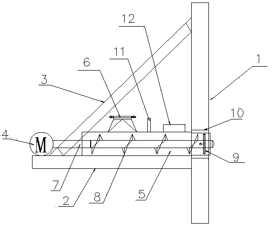
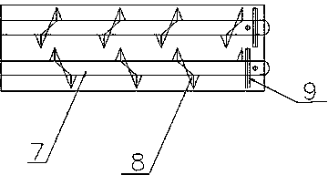
[0017] see figure 1 and figure 2 , the present invention includes a support seat 2 composed of a channel steel connected to the sludge conveying hole on the side wall of the sludge incinerator 1 . The motor 4 placed on the support base 2 is connected to the rotating shaft 7 through a reducer, and the rotating shaft 7 is provided with a helical blade 8 . The periphery of the rotating shaft 7 is provided with a sealed outer cylinder 5 with a circular or rectangular cross-section, and a square or circular material inlet 6 is arranged on the top of one end of the outer cylinder 5 . The support base 2 is fixed to the side wall of the sludge incinerator 1 through an obliquely arranged bracket 3, and the bracket 3 is made of channel steel. The rotating shaft 7 adopts two and is placed in parallel, and the motor 4 drives the two rotating shafts 7 to rotate oppositely by the shaft coupling after passing through the speed reducer. The ends of the two rotating shafts 7 are provided w...
PUM
 Abstract
Description
Claims
Application Information
 - Generate Ideas
- Intellectual Property
- Life Sciences
- Materials
- Tech Scout
- Unparalleled Data Quality
- Higher Quality Content
- 60% Fewer Hallucinations
Browse by: Latest US Patents, China's latest patents, Technical Efficacy Thesaurus, Application Domain, Technology Topic, Popular Technical Reports.
© 2025 PatSnap. All rights reserved.Legal|Privacy policy|Modern Slavery Act Transparency Statement|Sitemap|About US| Contact US: help@patsnap.com