Coating device and coating method for winding type sputtering three-layer dielectric film

A layer of dielectric film and coating device technology, which is applied in the field of vacuum coating equipment, can solve the problems of limited installation quantity, large equipment, and large production area, so as to achieve consistent sputtering target distance, accurate sputtering target distance, and prolong the film forming time Effect

Active Publication Date: 2014-05-21
深圳市锦瑞新材料股份有限公司
View PDF6 Cites 8 Cited by
  • Summary
  • Abstract
  • Description
  • Claims
  • Application Information

AI Technical Summary

Problems solved by technology

[0002] In the cathode sputtering film-forming device, the winding-type vacuum coating equipment can obviously improve the film-forming efficiency because of its continuous production. However, in the existing winding-type vacuum coating equipment, for each The number of membrane cathode chambers installed is limited, the sputtering time and sputtering atmosphere of each cathode chamber are difficult to accurately control, and the stability of film formation is poor. Most of them can only produce one or two layers of dielectric films, but cannot continuously sputter three layers of dielectric films. , because the sputtering film-forming time of the dielectric film in the middle of the three-layer dielectric film is longer, and the film-forming atmosphere is different from the atmosphere of the upper and lower dielectric films. The existing winding-type vacuum coating equipment rotates synchronously, and the single cathode chamber The sputtering film forming time is obviously not enough, and the atmosphere of each cathode chamber is also easy to interfere with each other;
[0003] In addition, the existing roll-to-roll vacuum coating equipment often needs to be used in conjunction with cleaning devices, heating devices, unwinding and winding mechanisms to form a production line, which will cause many equipment and occupy a large production area;

Method used


Image

  • Coating device and coating method for winding type sputtering three-layer dielectric film
  • Coating device and coating method for winding type sputtering three-layer dielectric film

Examples


Embodiment Construction

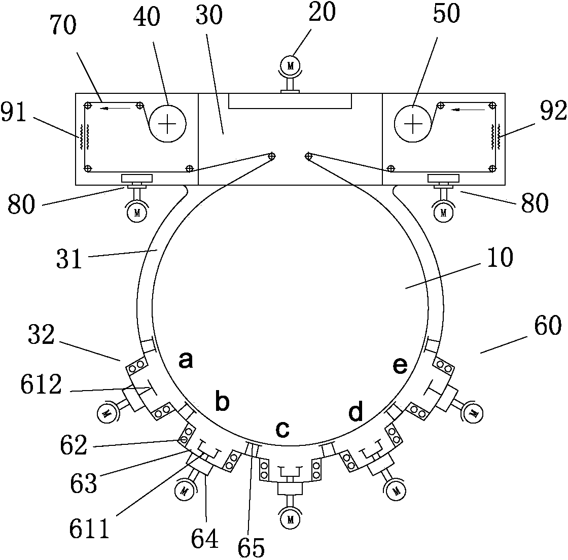
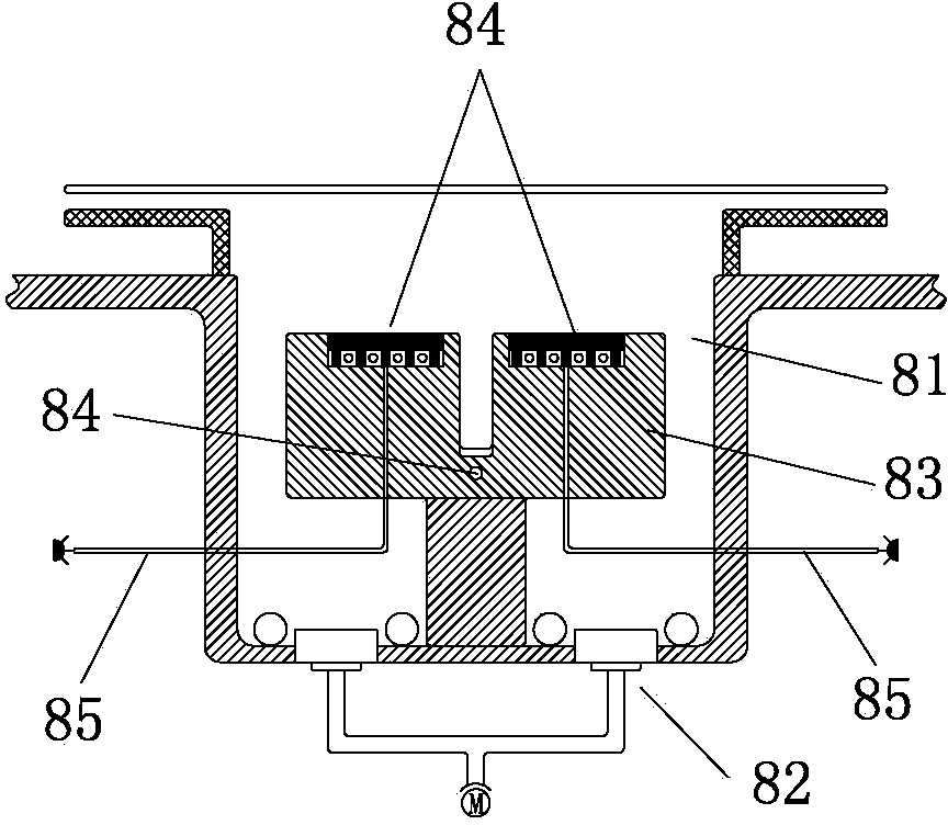
[0020] Such as Figure 1-2 As shown, a coating device for rolling sputtering three-layer dielectric film includes: a chill roll 10, a main motor 20 driving the chill roll 10, a vacuum chamber 30 covering the chill roll 10, and an unwinding mechanism 40. The winding mechanism 50 and five cathode cells 60, wherein the unwinding mechanism 40, the winding mechanism 50 and the five cathode cells 60 are all built in the vacuum chamber 30, and the unwinding mechanism 40 bypasses the cold roll through the raw film 70 The circumferential surface of 10 is transmitted to the winding mechanism 40 to realize the synchronous linkage of the three. The part of the vacuum chamber 30 covering the cold roll 10 is a cylindrical cavity 31, and five cathode cells 60 are arranged at intervals in the cylindrical cavity. On the inner wall of the body 31 and protruding outwards to form a cavity convex hull 32, the cathode small chamber 60 includes a cathode target body, a cooling water pipe 62, an air ...


PUM


Abstract

The invention relates to a coating device and a coating method for a winding type sputtering three-layer dielectric film. The coating device comprises a cold roller, a main motor for driving the cold roller, a vacuum cavity wrapping the cold roller, an unwinding mechanism, a winding mechanism and five cathode chambers, wherein the middle three cathode chambers of the five cathode chambers have the same structure which is a dual-target cathode chamber; the cathode targets in the dual-target cathode chamber are two cathode sputtering targets; the two cathode chambers on the two sides in the five cathode chambers have the same structure which is a single-target cathode chamber; the cathode target of the single-target cathode chamber is a cathode sputtering target. By adopting the structure, the middle three dual-target cathode chambers perform sputtering on the middle dielectric film of the three-layer dielectric film by use of the same atmosphere, thus the film forming time of the middle dielectric film is prolonged, and the sputtering target range of the dual-target cathode is more accurate.

Description

technical field [0001] The invention relates to a vacuum coating device, in particular to a coating device and a coating method applied to a winding-type sputtering three-layer dielectric film. Background technique [0002] In the cathode sputtering film-forming device, the winding-type vacuum coating equipment can obviously improve the film-forming efficiency because of its continuous production. However, in the existing winding-type vacuum coating equipment, for each The number of membrane cathode chambers installed is limited, the sputtering time and sputtering atmosphere of each cathode chamber are difficult to accurately control, and the stability of film formation is poor. Most of them can only produce one or two layers of dielectric films, but cannot continuously sputter three layers of dielectric films. , because the sputtering film-forming time of the dielectric film in the middle of the three-layer dielectric film is longer, and the film-forming atmosphere is diffe...

Claims


Application Information

Patent Timeline
Patent Type & Authority Applications(China)
IPC IPC(8): C23C14/42C23C14/56
Inventor 金烈
Owner 深圳市锦瑞新材料股份有限公司
Why Eureka
Try Eureka