Vent valve type exhaust brake system

A technology of exhaust brake and air release valve, which is applied in the direction of engine control, machine/engine, mechanical equipment, etc., can solve the problems of unreasonable structure of the braking system, engine damage, limited braking force, etc., and achieve easy control, Uniform braking force and simple structure

Inactive Publication Date: 2014-05-21
CHINA NORTH ENGINE INST TIANJIN
View PDF5 Cites 2 Cited by
  • Summary
  • Abstract
  • Description
  • Claims
  • Application Information

AI Technical Summary

Problems solved by technology

[0005] The technical problem to be solved by the present invention is to solve the problem that the braking system in the engine has unreasonable structure, limited braking force and other damage to the engine, and proposes an exhaust valve type exhaust braking system.

Method used


Image

  • Vent valve type exhaust brake system
  • Vent valve type exhaust brake system
  • Vent valve type exhaust brake system

Examples


Embodiment 1

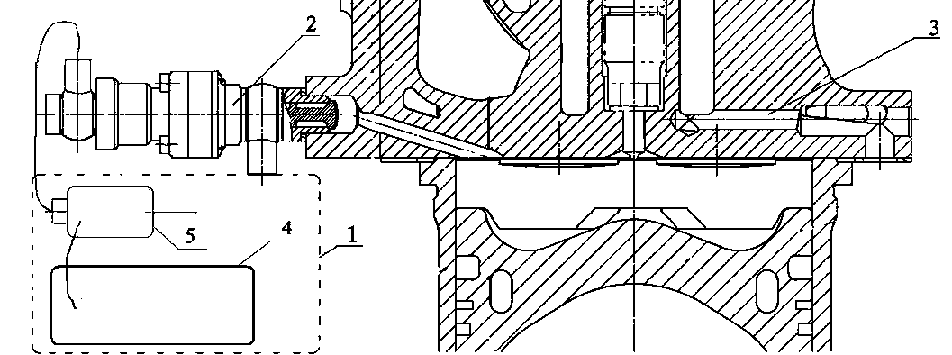
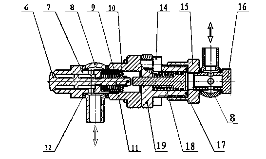
[0017] Such as figure 1 and figure 2 As shown, a bleed valve type exhaust brake system includes a control assembly 1, a brake assembly 2 and a cylinder head 3, the control assembly 1 includes an ECU electronic controller 4 and a hydraulically driven valve, and the brake assembly 2 includes a throttle valve 6. Air release valve sleeve 7, hollow ball joint 8, air release valve return spring 9, adjustment cap 10, brake valve end cover 11, gasket 12, screw 14, cylinder head 15, hollow bolt 16, piston 17, The return spring 18 and the cylinder liner 19, wherein the throttle valve 6 is set in the air release valve sleeve 7, the air release valve return spring 9 and the adjustment cap 10 are set on the throttle valve 6, and the air release valve return spring 9 and the adjustment cap 10 are installed In the brake valve end cover 11, the hollow ball joint 8 is set between the brake valve end cover 11 and the air release valve sleeve 7, and is sealed by the gasket 12, the screw 14 is ...

Embodiment 2

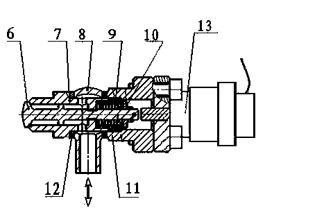
[0022] Such as figure 1 and image 3 As shown, a bleed valve type exhaust brake system includes a control assembly 1, a brake assembly 2 and a cylinder head 3, the control assembly 1 includes an ECU electronic controller 4 and an electromagnetic drive valve, and the brake assembly 2 includes a throttle valve 6. Air release valve sleeve 7, hollow ball joint 8, air release valve reset spring 9, adjustment cap 10, brake valve end cover 11, gasket 12 and electromagnetic push rod, among which the throttle valve 6 is set on the air release valve sleeve 7, the air release valve return spring 9 and the adjustment cap 10 are set on the throttle valve 6, the air release valve return spring 9 and the adjustment cap 10 are installed in the brake valve end cover 11, and the hollow ball joint 8 is set on the brake valve Between the valve end cover 11 and the deflation valve sleeve 7, it is sealed by a gasket 12; the ECU electronic controller 4 is connected with the drive valve 5, and the d...


PUM


Abstract

The invention relates to a vent valve type exhaust brake system. A throttle valve (6) is arranged in a vent valve sleeve (7) and sleeved with a vent valve reset spring (9) and an adjusting cap (10), the vent valve reset spring (9) and the adjusting cap (10) are installed in a brake valve end cover (11), and a hollow spherical connector (8) is installed between the brake valve end cover (11) and the vent valve sleeve (7) in a sleeved mode and sealed by a sealing gasket (12); an ECU (4) is connected with a drive valve (5), the drive valve (5) is connected with a control device (13) on a brake assembly (2), and the vent valve sleeve (7) on the brake assembly (2) is connected with an air cylinder cover (3). The vent valve type exhaust brake system is uniform in brake force, brake performance of the vent valve type exhaust brake system is the same as the brake performance of an engine vent valve, damage to an engine is not caused, and the vent valve type exhaust brake system is compact in structure and easy to achieve.

Description

technical field [0001] The invention belongs to the technical field of vehicle braking, and in particular relates to an exhaust valve type exhaust braking system. Background technique [0002] At present, there are two types of exhaust brakes commonly used in domestic vehicle engines. [0003] One is the exhaust pipe exhaust brake, which adopts the structural form of installing an exhaust butterfly valve in the exhaust pipeline. The advantage is that the structure is simple and easy to implement; the disadvantage is that the braking force is limited, which may damage the engine, especially for the exhaust. The door creates a reverse impact force. [0004] The other is engine exhaust valve exhaust braking. By adding an auxiliary opening mode to the exhaust valve, the exhaust valve is opened a small amount after receiving the braking signal, resulting in lax closing and forming the exhaust valve throttling effect And consume energy, the advantage of this method is that the ...

Claims


Application Information

Patent Timeline
IPC IPC(8): F02D9/06F02D9/08
Inventor 王增全马宁刘烨周海涛
Owner CHINA NORTH ENGINE INST TIANJIN
Why Eureka
Try Eureka