

Center-shaft-type cylindrical roller bearing
A cylindrical roller bearing and cylindrical roller technology, applied in the field of machinery, can solve the problems of high noise, low safety factor and low speed.
Inactive Publication Date: 2014-05-21
李岚
View PDF0 Cites 6 Cited by
- Summary
- Abstract
- Description
- Claims
- Application Information
AI Technical Summary
Problems solved by technology
It solves the shortcomings of the existing cylindrical roller bearings such as low load capacity, high noise, short life, low safety factor and low speed
Method used
View moreImage
Smart ImageViewing Examples

Examples
Embodiment approach
[0017] DETAILED DESCRIPTION OF THE PREFERRED EMBODIMENTS Inventing a central axis cylindrical roller bearing: specific examples figure 2 shown;
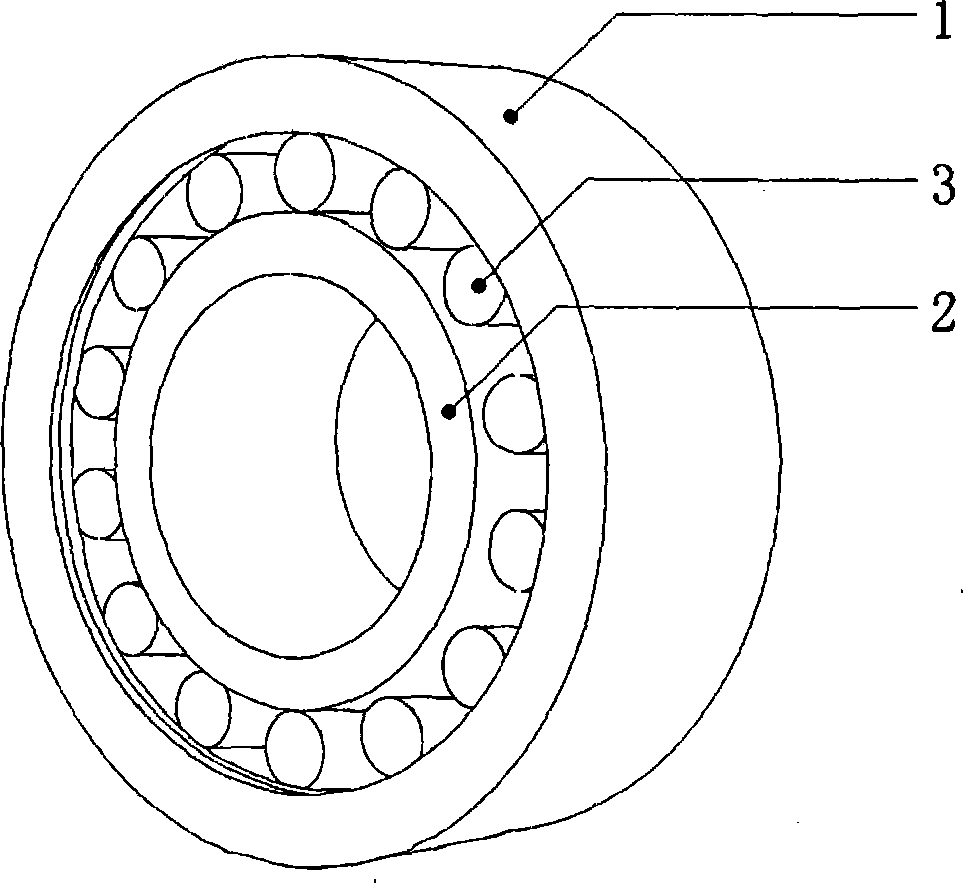
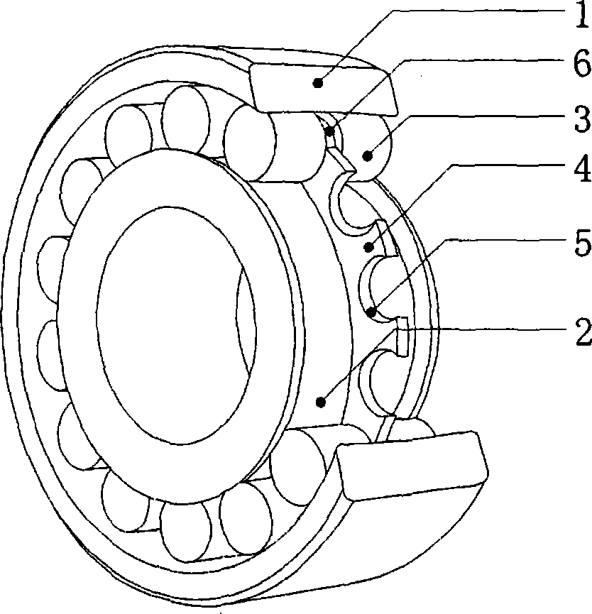
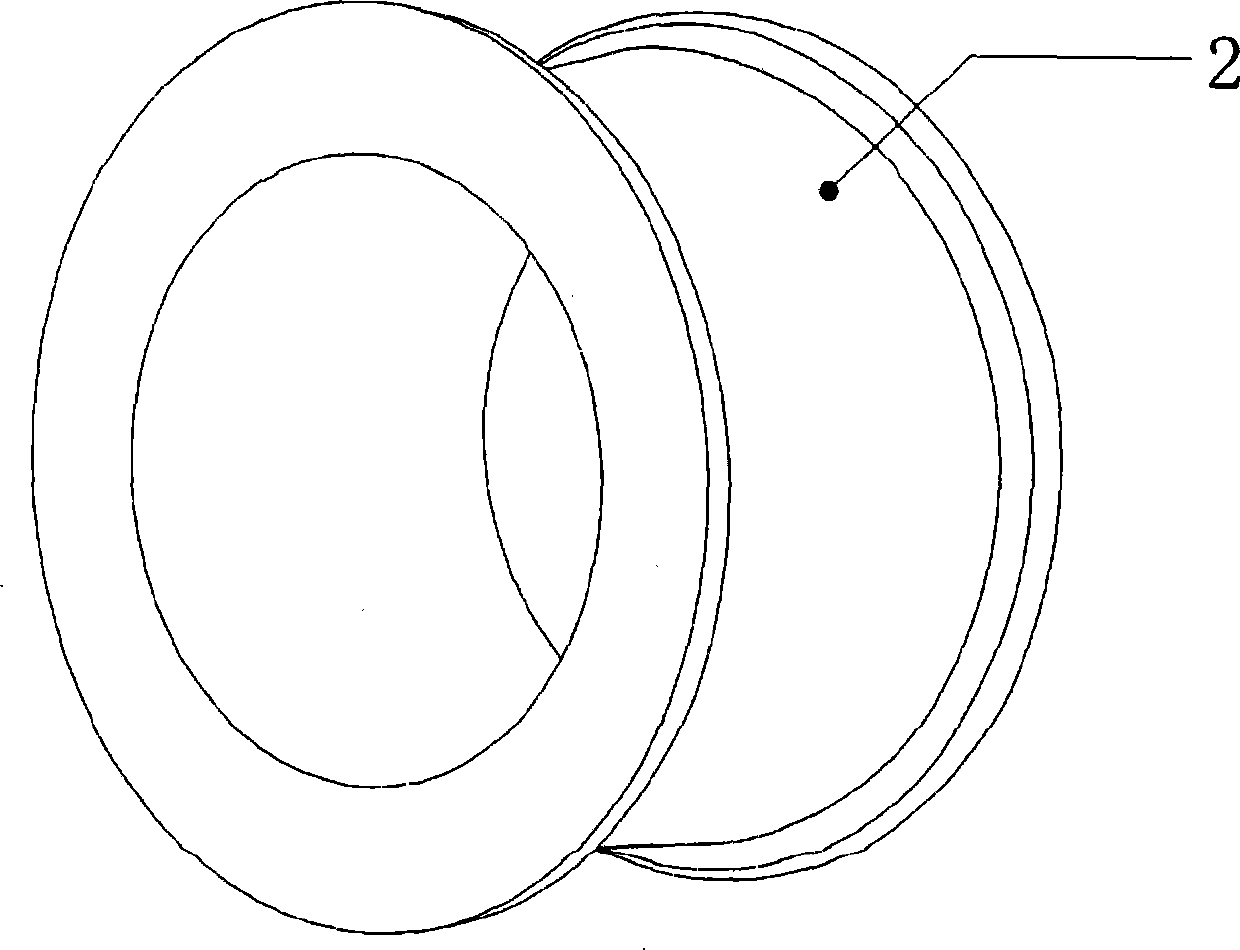
[0018] Installation steps: The outer circular raceway of the inner ring (2) is relatively matched with the annular C-shaped mouth cage (4) or (8), and the C of the C-shaped mouth shape cage (4) and (8) Insert the center shaft type cylindrical roller (3) on the shape mouth (5) or (9) to match it, then insert the inner ring (2) and the center shaft type cylindrical roller (3) to the inner hole of the outer ring Among them, the relative combination in the inner hole of (1) is figure 1 Bottom shaft cylindrical roller bearing shown here.
Login to View More PUM
 Abstract
The invention discloses a center-shaft-type cylindrical roller bearing. The center-shaft-type cylindrical roller bearing comprises an inner sleeve ring, an outer sleeve ring, a row of cylindrical waist-diameter sunken center shaft rollers and a rolling circular ring retainer; an excircle roller way of the inner sleeve ring or a roller way of the outer sleeve ring is internally sleeved with a rolling circular ring C-shaped retainer; the center-shaft-type cylindrical roller is embedded in a C opening of the rolling circular ring C-shaped retainer; the center-shaft-type cylindrical roller is fully filled with the C-shaped retainer while the outer sleeve ring is arranged. A bearing surface is increased by increasing the number of the rollers so as to improve the load capacity of the bearing; the noise is reduced by reducing the frictional surfaces of the retainer and the rollers, and the service life of the bearing is prolonged.
Description
technical field [0001] The invention relates to the field of machinery, replaces the existing cylindrical roller bearing, and is a practical and innovative bearing used in the same optical-motor integration. Background technique [0002] In the era of rapid development of global machinery and equipment, the existing traditional bearing structure can no longer meet the technical needs of the development of machinery and equipment. Take the spherical roller bearing installed in the existing mechanical equipment as an example; the bearing structural support features are: inner ring, outer ring, single or double row cylindrical roller; brass frame cage combined into a set of cylindrical roller bearings . Spherical roller bearings have single or double row rollers, large radial load capacity, and are suitable for bearing heavy loads and shock loads. N type and NU type can move axially, can adapt to the change of the shaft and shell due to thermal expansion or the same, and can ...
Claims
Login to View More Application Information
Patent Timeline
 IPC IPC(8): F16C33/54F16C33/58F16C33/66
Inventor李岚
Owner李岚