Afterburning burner for gas turbine waste heat boiler

A waste heat boiler and gas turbine technology, which is applied to the combustion of block fuel and gaseous fuel, the combustion of liquid fuel and gaseous fuel, and gas fuel burners, etc., can solve the problem that the exhaust gas contains toxic and harmful components and the combustion of chemical exhaust gas is insufficient. , burner pipe heating and other problems, to achieve the effect of easy replacement and maintenance operations, short flame, and stable flame

Active Publication Date: 2014-05-21
JINAN TORCH CREATION ENERGY SCI & TECH
View PDF7 Cites 3 Cited by
  • Summary
  • Abstract
  • Description
  • Claims
  • Application Information

AI Technical Summary

Problems solved by technology

At present, there is no burner component in the waste heat boiler. If the ordinary burner is directly used in the waste heat boiler, the problems caused are: First, because the air content in the high-temperature flue gas is relatively low compared with the oxygen content in ordinary air, so that Insufficient combustion of chemical tail gas causes toxic and harmful components in the secondary exhaust gas; second, the high-temperature flue gas used as an air source has a high temperature (up to 200 to 800 ° C), which easily causes the temperature of the pipe in the burner to rise, and then It will cause carbonization of the chemical tail gas in the pipe, block the spray gun, and affect the service life; the third is that there is a safety hazard when dealing with chemical tail gas containing hydrogen and other low flash explosion points.

Method used


Image

  • Afterburning burner for gas turbine waste heat boiler
  • Afterburning burner for gas turbine waste heat boiler
  • Afterburning burner for gas turbine waste heat boiler

Examples


Embodiment Construction

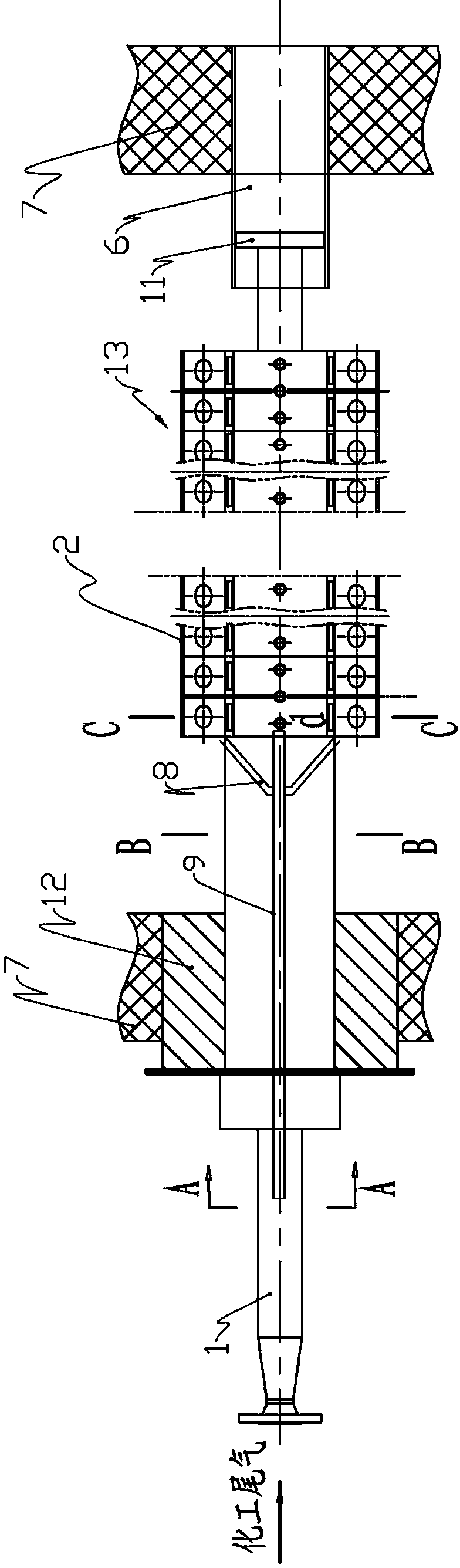
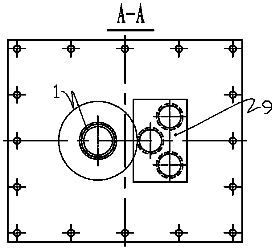
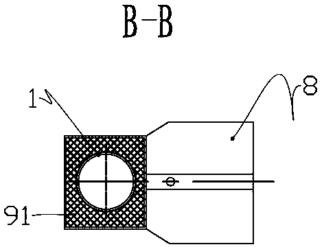
[0032] Such as Figure 1 to Figure 5 as shown,

[0033] A post-combustion burner for a gas turbine waste heat boiler, comprising a chemical tail gas pipe, an ignition device and a monitoring device.

[0034] The chemical exhaust pipe 1 is a straight pipe made of stainless steel, and one end of the chemical exhaust pipe 1 is an interface for connecting a toxic chemical exhaust gas source, which is used to connect with the chemical exhaust gas, and the connection form is a flange connection. The other end of the chemical tail gas pipe 1 is closed, that is, in the form of a blind pipe, and a mounting square plate 11 is welded and fixed at the closed end. The mounting square plate 11 is plugged and connected with the inner wall 7 of the gas turbine waste heat boiler through a connecting piece 6 . At the same time, there is also an installation part 12 on the pipe of the chemical exhaust pipe 1 for cooperating with the waste heat boiler of the gas turbine. The size of the installa...


PUM


Abstract

The invention discloses an afterburning burner for a gas turbine waste heat boiler. The afterburning burner for the gas turbine waste heat boiler comprises a chemical engineering tail gas pipe, an ignition device and a flame stabilizing component; one side of a burning part of the chemical engineering tail gas pipe is provided with a plurality of ranked spray holes; a spray pipe extends vertically outwards from the spray holes; the cross sectional area of a gas flow channel of the spray pipe is 10-20 times of the cross sectional areas of the spray holes; the flame stabilizing component comprises inner flame stabilizing covers and outer flame stabilizing covers, wherein the inner flame stabilizing covers and the outer flame stabilizing covers are of V-shaped structures; the inner flame stabilizing covers are formed integrally and are sequentially provided with V-shaped grooves, flat bases and oblique walls from the centers to two sides; each outer flame stabilizing cover is sequentially provided with a first through hole and a second through hole which are parallel to the spray pipe from inward to outward. The afterburning burner for the gas turbine waste heat boiler, which is provided by the invention, has the characteristics of being short in flames, complete in burning, high in flame intensity and reasonable in smoke distribution, and is suitable for waste heat boilers, so that high-temperature smoke and toxic chemical engineering tail gases in industry can be treated effectively in a combined mode by the waste heat boiler.

Description

technical field [0001] The proposal belongs to the technical field of industrial burners, and specifically relates to a post-combustion burner for gas turbine waste heat boilers. Background technique [0002] The waste heat boiler refers to the boiler that uses the sensible heat in the high-temperature flue gas generated in various industrial processes and achieves the purpose of external work through heat exchange. It does not need fuel supply itself. The principle is that the high-temperature flue gas is transported to the waste heat boiler through the pipeline, the cold water in the waste heat boiler is heated through heat exchange, and the high-temperature flue gas is cooled at the same time, so as to achieve secondary utilization of the high-temperature flue gas. [0003] For the chemical tail gas generated in the chemical production process, because the chemical tail gas contains toxic components, such as carbon monoxide, hydrogen, hydrogen sulfide and other toxic and ...

Claims


Application Information

Patent Timeline
Patent Type & Authority Applications(China)
IPC IPC(8): F23C5/08F23D14/58F23D14/72
Inventor 杜建吉
Owner JINAN TORCH CREATION ENERGY SCI & TECH
Why Eureka
Try Eureka