Cable Partial Discharge Test Equipment Based on Optical Electric Field Sensor Voltage Phase Synchronization Technology

A sensor voltage and phase synchronization technology, applied in the direction of testing dielectric strength, etc., can solve the problems of partial discharge spectrum phase relationship error, voltage and current phase angle difference change, voltage phase can not be obtained, etc., to achieve fast waveform response and ensure accuracy Sexuality, the effect of ensuring adverse consequences

Active Publication Date: 2017-03-22
ELECTRIC POWER RES INST OF GUANGXI POWER GRID CO LTD
View PDF5 Cites 0 Cited by
  • Summary
  • Abstract
  • Description
  • Claims
  • Application Information

AI Technical Summary

Problems solved by technology

This is an indirect method, because in the field test, the parameters of the line will vary greatly with the influence of voltage level, cable length, overhead line length, system operation, line space position, and load. Therefore, the voltage and current The phase angle difference will also change. If the phase conversion is performed only through certain experience, then not only cannot the accurate voltage phase be obtained, but also may cause misjudgment due to the wrong phase relationship of the partial discharge map.
[0004] It is difficult to estimate the loss of materials and electricity caused by misjudgments or inaccurate judgments that lead to unnecessary power outages and maintenance of cable lines; and the emergency repairs and electricity caused by cable lines that still fail after testing due to missed judgments The loss is far greater than the loss caused by accurate judgment and planned maintenance
[0005] There is no report of similar device of the present invention at present

Method used


Image

  • Cable Partial Discharge Test Equipment Based on Optical Electric Field Sensor Voltage Phase Synchronization Technology

Examples


Embodiment Construction

[0022] The present invention will be further described below in conjunction with the accompanying drawings and specific implementation.

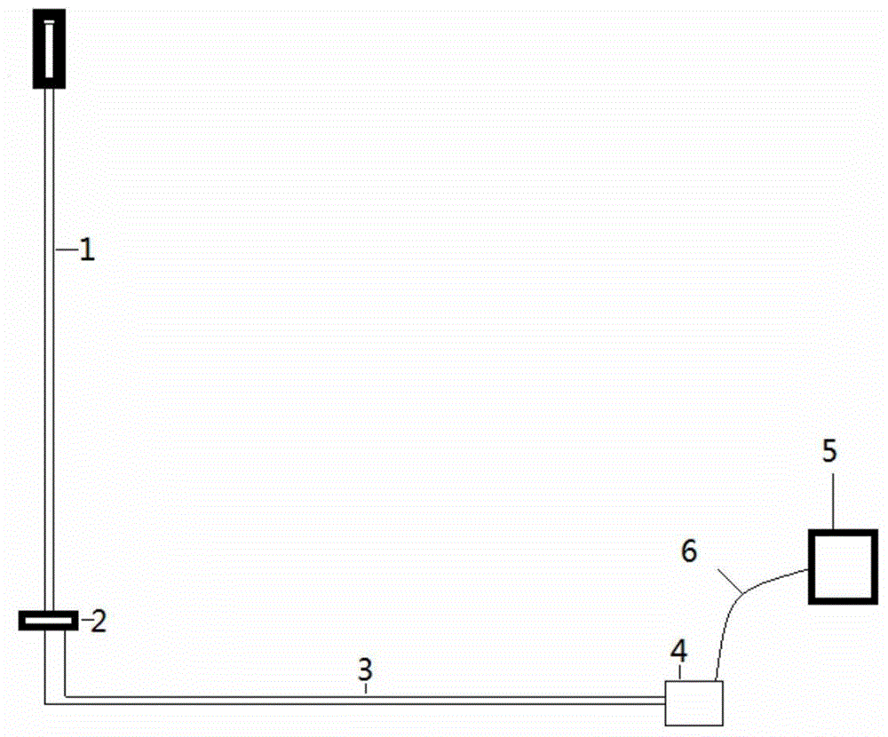
[0023] The structure of the cable partial discharge test equipment based on the optical electric field sensor voltage phase synchronization technology of the present invention is as follows: figure 1 As shown, the device is composed of a hand-held insulating tool 1, a high-voltage BGO optical crystal 2, a high-voltage optical fiber 3, a photoelectric conversion and output device 4, a partial discharge test instrument 5, and a synchronization signal transmission line 6.

[0024] The hand-held insulating tool 1 has one end as a hand-held end, which can be operated by the operator or can be fixed at a desired position; the middle part is a hard insulating part, which can be used for insulating operations including those that meet high-voltage insulation standards on the market. The other end is a high-voltage end, which is equipped with a certa...


PUM


Abstract

The invention discloses test equipment for partial discharge of a cable based on a voltage phase synchronization technology of an optical electric field transducer. The test equipment comprises a handhold insulated tool and instrument, a high voltage BGO optical crystal, a high voltage optical fiber, a photoelectric conversion and output unit, a partial discharge test instrument and a synchronous signal transmission wire. The test equipment disclosed by the invention has the advantages that: the test equipment emphatically solves the difficulty in acquirement and synchronization of a voltage signal in a major network during live line test works of field high voltage equipment, is also applicable to any work that needs acquirement of the voltage signal during electrical test; the test equipment is simple and firm in structure, light in weight (less than 1kg), small in volume and convenient in operation on a basis that functional requirements are met, and is applicable to the requirements on live tests of equipment on a pole and a tower as well as ground equipment.

Description

technical field [0001] The invention relates to the working field of electrical performance testing of electric power equipment. Specifically, it is a cable partial discharge test equipment based on optical electric field sensor voltage phase synchronization technology. Background technique [0002] In the current market, partial discharge testing instruments are widely used when performing partial discharge non-stop power testing on cable equipment. There are many manufacturers of such instruments, but the common feature is that they all need to obtain the voltage sine wave data of the primary system of the power grid during the test, including frequency signals, voltage phase signals, etc. The function of this signal is to display the real-time voltage phase signal, and then mark the partial discharge signal captured by the partial discharge instrument at the corresponding phase and signal strength on the voltage phase signal according to the time relationship and signal ...

Claims


Application Information

Patent Timeline
Patent Type & Authority Patents(China)
IPC IPC(8): G01R31/12
Inventor 陈智勇唐捷刘聪汉李恒灿韦魏
Owner ELECTRIC POWER RES INST OF GUANGXI POWER GRID CO LTD
Why Eureka
Try Eureka