Clamp diode, layout structure thereof and manufacturing method thereof

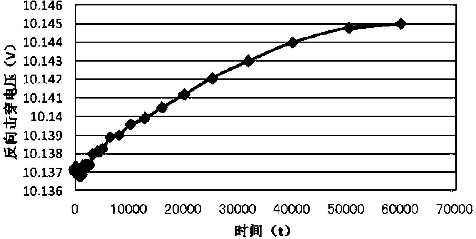
A clamping diode and high-resistance technology, which is applied in semiconductor/solid-state device manufacturing, electrical components, circuits, etc., can solve the problems of unfavorable integrated circuit miniaturization, increased integrated chip area, and high integrated circuit manufacturing cost, and achieve reverse Improved leakage characteristics and reduced device reverse leakage

Inactive Publication Date: 2014-05-21
SHANGHAI HUAHONG GRACE SEMICON MFG CORP
View PDF5 Cites 4 Cited by
  • Summary
  • Abstract
  • Description
  • Claims
  • Application Information

AI Technical Summary

Problems solved by technology

In actual use, BGR circuits are usually used for applications with high-precision voltage requirements, but BGR circuits use too many electronic devices, resulting in high manufacturing costs for integrated circuits and increasing the area of ​​integrated chips, which is not conducive to the development of integrated circuits. miniaturization

Method used


Image

  • Clamp diode, layout structure thereof and manufacturing method thereof
  • Clamp diode, layout structure thereof and manufacturing method thereof
  • Clamp diode, layout structure thereof and manufacturing method thereof

Examples


Embodiment Construction

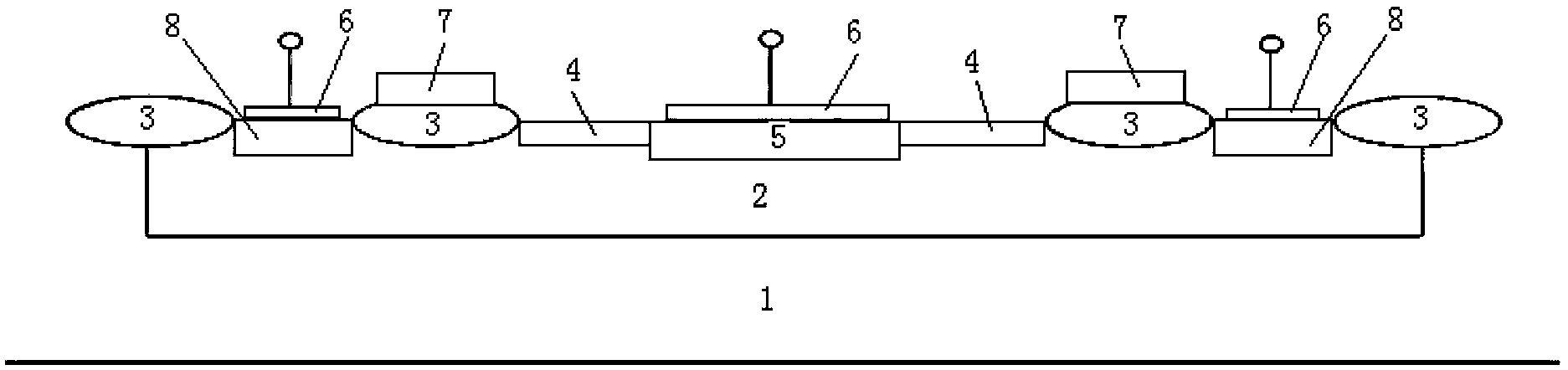
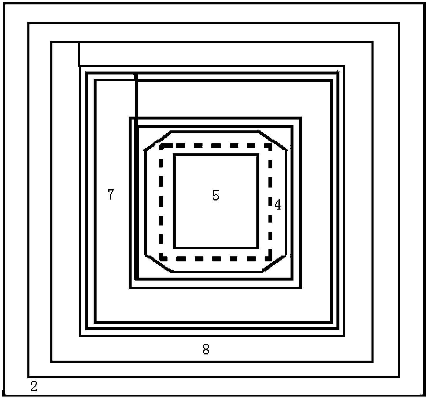
[0038] Such as figure 1 As shown, the clamping diode of the present invention includes:

[0039] The N-type well region 2 on the P-type substrate 1, the P-type high-resistance region 4 on the top of the N-type well region 2, and the P-type low-resistance region 5 between the P-type high-resistance regions 4, and the P-type high-resistance region 4. There is an insulating region 3 on the outside, an N+ doped region 8 is located between the two insulating regions 3 on the same side of the P-type high-resistance region 4, and a polysilicon layer 7 is provided on the insulating region 3 adjacent to the P-type high-resistance region 4. There is a metal silicide 6 on the type low resistance region 5 and the N+ doped region 8;

[0040] The P-type high-resistance region 4 and the P-type low-resistance region 5 lead out through the metal silicide 6 to form the anode of the clamping diode;

[0041] The N+ doped region 8 leads out through the metal silicide 6 to form the cathode of the...


PUM


Abstract

The invention discloses a clamp diode comprising an N type well region on a P type substrate, P type high resistance regions at the upper part of the N type well region, a P type low resistance region between the P type high resistance regions, insulated regions at the outer sides of the P type high resistance regions, N+ deposed regions between the two insulated regions at the same side of P type high resistance regions, polysilicon layers on the insulated regions adjacent to the P type high resistance regions, and metal silicide on the P type low resistance region and the N+ deposed regions. The P type high resistance regions and the P type low resistance region are led out through the metal silicide to form the anode of the clamp diode, the N+ deposed regions are led out through the metal silicide to form the cathode of the clamp diode, and the polysilicon layers and an anode lead-out end are in short circuit connection. The invention also provides the layout structure of the clamp diode and a manufacturing method of the clamp diode. The function of a BGR circuit in a high precision voltage requirement application can be replaced by the clamp diode, the manufacturing cost of a circuit can be reduced at the same time, the integrated chip area is reduced, and the miniaturization of an integrated circuit is facilitated.

Description

technical field [0001] The invention relates to the field of semiconductor manufacturing, in particular to a clamping diode. The present invention also relates to a layout structure of the clamping diode and a manufacturing method of the clamping diode Background technique [0002] Clamping diodes are widely used in integrated circuits to play the role of clamping voltage, such as clamping diodes in ESD protection circuits. Usually these circuits do not have high requirements on the accuracy of the clamping voltage, including the in-plane distribution of the clamping voltage, and the time dependence, temperature dependence, leakage and other indicators of the existing clamping diodes used in the clamping circuit are not very high. Requirements, the existing clamping diodes are usually integrated with some process parasitics, and the use of the existing clamping diodes will not increase the process cost. In actual use, BGR circuits are usually used for applications with hig...

Claims


Application Information

Patent Timeline
Patent Type & Authority Applications(China)
IPC IPC(8): H01L29/861H01L29/06H01L21/329
CPCH01L29/8611H01L29/0684H01L29/66128
Inventor 仲志华祝奕琳
Owner SHANGHAI HUAHONG GRACE SEMICON MFG CORP
Why Eureka
Try Eureka