Optical fiber radiation source with adjustable radiation energy and wavelength

A technology of radiant energy and radiation source, applied in the field of radiation source, can solve the problems of increasing test error, difficulty in precise alignment, impossibility of realization, etc., and achieve the effect of precise calibration

Active Publication Date: 2014-05-28
CHINA ELECTRONIS TECH INSTR CO LTD
View PDF4 Cites 4 Cited by
  • Summary
  • Abstract
  • Description
  • Claims
  • Application Information

AI Technical Summary

Problems solved by technology

When using this radiation source to calibrate instruments such as spectrometers and photodetectors, it is necessary to align the calibration instrument with the exit aperture of the radiation source. When the position of the calibration instrument or the direction of the receiving beam changes, it is necessary to move the entire radiation The source is used to align the beam output aperture with the receiving surface of the calibration instrument, which is cumbersome to operate and difficult to align accurately
In addition, in this radiation source, the radiation energy of a single wavelength is not adjusted, and the test of the spectral responsivity of the calibration instrument under the irradiation of different radiation energies cannot be realized, which affects the test accuracy and increases the test error
[0005] Disadvantages of the existing technology: 1. The existing adjustable monochromatic radiation source cannot realize the large dynamic range adjustment of the radiation energy of a single wavelength, thereby affecting the calibration accuracy of the spectral responsivity; 2. When the position of the spectrometer, photodetector and other instruments Or when the direction of the beam receiving surface changes, it is necessary to move the entire radiation source to realize the change of the beam propagation direction, which is inconvenient to use and difficult to align

Method used


Image

  • Optical fiber radiation source with adjustable radiation energy and wavelength

Examples


Embodiment 1

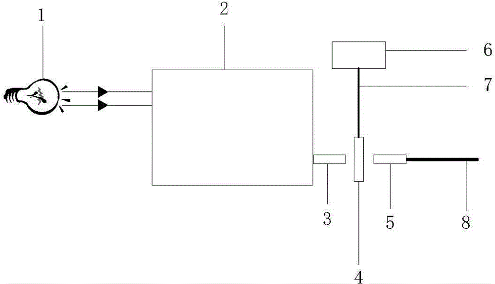
[0022] Such as figure 1 As shown, the present invention proposes a fiber optic radiation source with adjustable radiant energy and wavelength, mainly composed of a light source 1, a monochromator 2, an input collimator 3, an attenuation sheet 4, an output collimator 5, and a stepping motor 6 , a stepping motor screw 7 and an optical fiber 8. The monochromator 2 is mainly composed of an incident slit, an exit slit and a rotatable grating. The light source 1 is aligned with the incident slit of the monochromator 2, and the input collimator 3 is installed at the exit slit of the monochromator 2. , the attenuator 4 is located between the input collimator 3 and the output collimator 5, the stepper motor 6 is connected to the attenuator 4 through the stepper motor screw 7, and the input port of the optical fiber 8 is connected to the output port of the output collimator 5 .

[0023] The light emitted by the light source 1 is continuous light, which enters the monochromator 2 throu...


PUM


Abstract

The invention provides an optical fiber radiation source with adjustable radiation energy and wavelength. The optical fiber radiation source comprises a light emitting source, a monochromator, an input collimator, an attenuation slice, an output collimator, a stepper motor, a stepper motor screw and an optical fiber. The light emitting source is directed at an incidence slit of the monochromator. The input collimator is arranged in an emergence slit of the monochromator. The attenuation slice is located between the input collimator and the output collimator. The stepper motor is connected with the attenuation slice through the stepper motor screw, so as to control the movement of the attenuation slice. The input port of the optical fiber and the emergence port of the output collimator are connected. According to the scheme, by adjusting the monochromator and the attenuation ratio of the attenuation slice, the radiation source with adjustable radiation energy and wavelength is realized; the optical fiber is used to output a beam, thus the propagation direction of the beam can be conveniently changed; and the requirements of adjustable radiation energy and wavelength of the radiation source and flexible change of the beam direction are satisfied when calibration is carried out on a spectrometer, a photoelectric detector and the like.

Description

technical field [0001] The invention belongs to the technical field of radiation sources, in particular to an optical fiber radiation source with adjustable radiation energy and wavelength. Background technique [0002] In the development of spectrometers, photodetectors, satellite remote sensing optical sensors, cameras and other instruments, in order to ensure the accuracy of spectral information and detection data, it is necessary to perform precise radiation calibration on spectrometers and photodetectors to ensure the accuracy of the instruments . When calibrating instruments such as spectrometers and photodetectors, radiation sources are usually used to directly irradiate the instruments to achieve spectral responsivity calibration. [0003] In practical applications, instruments such as spectrometers and photodetectors have a certain working wavelength range, and the spectral responsivity is related to the wavelength. Therefore, it is necessary to use a single wavele...

Claims


Application Information

Patent Timeline
Patent Type & Authority Applications(China)
IPC IPC(8): G01J3/28G01J3/18G02B26/02
Inventor 聂建华张鹏
Owner CHINA ELECTRONIS TECH INSTR CO LTD
Why Eureka
Try Eureka