Hydraulic Mechanical Rotary Braking Energy Recovery Device
A technology of slewing braking energy and hydraulic machinery, applied in the direction of brakes, braking components, transportation and packaging, etc., can solve problems such as lower than set value and waste, and achieve the effect of low price and mature technology
- Summary
- Abstract
- Description
- Claims
- Application Information
AI Technical Summary
Problems solved by technology
Method used
Image
Examples
Embodiment 1
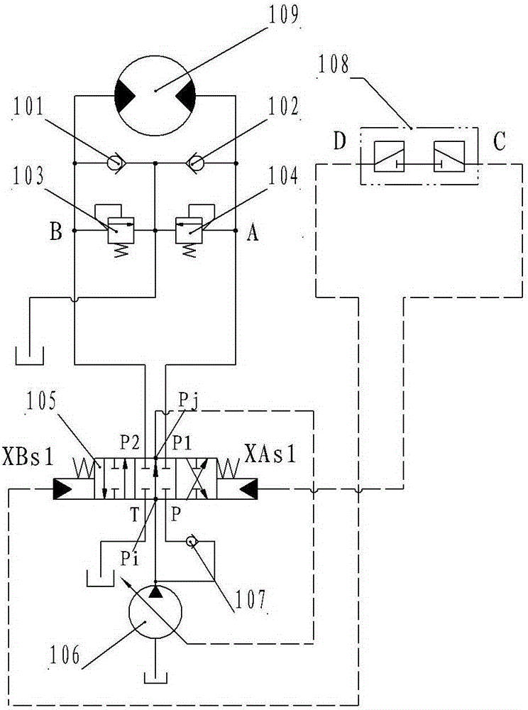
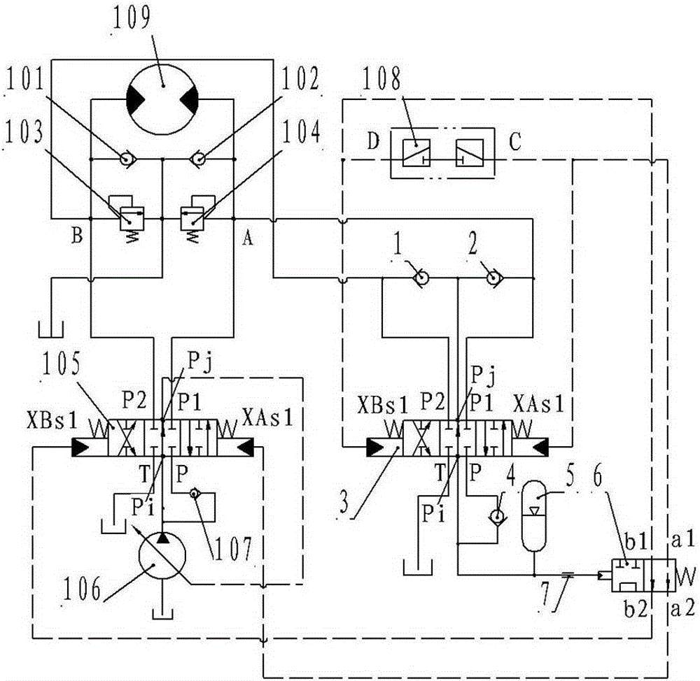
[0017] Embodiment 1: This hydraulic mechanical rotary braking energy recovery device, the hydraulic principle diagram is as follows figure 2 As shown, it includes a hydraulic motor 109 that drives the rotary parts, a variable oil pump 106 that provides the driving medium to the hydraulic motor 109, and a variable oil pump 106 and the hydraulic motor 109 are connected with a center function and closed at the same time. The first hydraulic control reversing valve 105 with four oil ports, in which chamber A and chamber B of the hydraulic motor 109 are respectively connected to the oil ports (P1) and (P2) of the first hydraulic control reversing valve 105, the first hydraulic control A check valve 107 is connected between the first oil inlet (P) of the reversing valve 105 and the oil outlet of the variable oil pump 106. The oil port (T) of the first hydraulic control reversing valve 105 communicates with the oil tank, and the first The liquid control end of the hydraulic control ...
PUM
 Abstract
Description
Claims
Application Information
 - R&D
- Intellectual Property
- Life Sciences
- Materials
- Tech Scout
- Unparalleled Data Quality
- Higher Quality Content
- 60% Fewer Hallucinations
Browse by: Latest US Patents, China's latest patents, Technical Efficacy Thesaurus, Application Domain, Technology Topic, Popular Technical Reports.
© 2025 PatSnap. All rights reserved.Legal|Privacy policy|Modern Slavery Act Transparency Statement|Sitemap|About US| Contact US: help@patsnap.com


