Solar energy and building integrated hot air power generation, ventilation and heating system

A technology of heating system and solar energy, which is applied in the field of combined hot air power generation and building heat storage heating, which can solve the problems of power consumption, large energy consumption, and waste of heat energy, so as to improve the guarantee rate and reliability, and improve the utilization Efficiency, efficient and rational use of the effect

Active Publication Date: 2014-06-04
山西奥通光热技术有限公司
View PDF6 Cites 9 Cited by
  • Summary
  • Abstract
  • Description
  • Claims
  • Application Information

AI Technical Summary

Problems solved by technology

This technology obviously has the following problems: 1. At present, the power generation efficiency of solar thermal airflow is lower than 1%, while the low-temperature solar thermal conversion efficiency of solar energy is higher than 50%. If the hot air generated by solar energy is used for power generation in winter without heating, Then there is the problem of low efficiency utilization of solar energy; 2. Only use the roof of the building to install the solar air heat collector, the installation area of ​​the solar air heat collector is small, and the system efficiency is low; 3. The device installs the solar heat storage device on the roof, increasing 4. There cannot be a good combination between solar thermal power generation technology and building energy demand
This technology proposes to use air as the heat transfer medium and phase-change heat storage materials as the heat storage medium to realize solar heating and ventilation through a combination of active and passive methods. The method uses the glass roof in the heat storage space for lighting, and the solar light directly It is irradiated on the phase change heat storage material to heat it, and then the phase change heat storage material heats the surrounding air. When necessary, the fan blows the hot air in the heat storage space into the room to achieve the goal of heating. When ventilation is required, the heat storage space is turned on. The vents on both sides of the thermal space realize natural ventilation or fan forced ventilation. This technology uses phase-change heat storage materials for heat storage and heating. Because the building consumes a lot of energy, it requires a large amount of heat storage materials. The phase-change materials store heat The cost is high. This technology adopts natural ventilation or fan forced ventilation, which cannot achieve effective ventilation when there is no wind and no electricity, and relying on fan ventilation requires additional power consumption
The following problems obviously exist in the two technologies: 1. The problem of waste of solar energy resources
[0006] 1. Unreasonable use of hot air flow generated by solar energy
At present, the efficiency of solar hot air power generation technology is generally lower than 1%, while the efficiency of solar low-temperature hot air heating technology is higher than 30%. If the hot air generated by solar energy is used for power generation instead of heating during the heating period, there will be low efficiency utilization of solar energy. problem; on the other hand, in the non-heating period, the building does not need a lot of heat energy, the heat of the hot air generated by the collector in the solar hot air heating technology cannot be used, resulting in waste of heat energy, and the temperature of the collector is too high, which is harmful to The heat collector is unfavorable, and at this time the electricity needed by the building cannot be met by solar heating technology
[0007] 2. The above-mentioned solar hot air power generation technology and solar heating technology have not considered meeting the needs of building domestic hot water and ventilation in summer
[0008] 3. The above-mentioned building roof-type solar thermal airflow power generation technology only uses the solar air collector installed on the roof of the building. The installation area of ​​the solar air collector is small, the system efficiency is low, and the integration degree of the solar air collector and the building is poor. duplicate build problem

Method used


Image

  • Solar energy and building integrated hot air power generation, ventilation and heating system
  • Solar energy and building integrated hot air power generation, ventilation and heating system
  • Solar energy and building integrated hot air power generation, ventilation and heating system

Examples


Embodiment 2

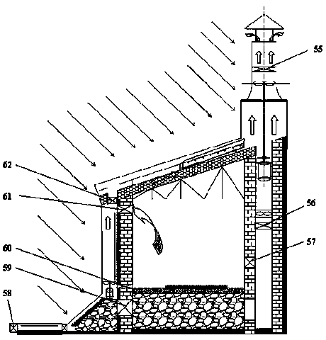
[0038] Embodiment 2: on the basis of embodiment 1, will be in Figure 5 The X-type interlayer air inlet duct 38 in the middle is made into a single-passage cross-sectional shape that is a rectangular or circular pipe shape, such as Figure 6 As shown, at this time, a confluence groove 66 is designed below the air inlet 65, a ventilation hole 67 is designed below the air inlet duct, and a valve 68 is designed at the ventilation hole 67. There can be one ventilation hole 67 and the valve 68, or one There are 2 to 3. What needs to be explained is that the sandwich-type air inlet duct has small wind resistance and large heating area, but the construction cost is high, while the single-channel duct-shaped air duct with a rectangular or circular cross-section shape is low in construction cost, but the convection heating efficiency is relatively low. poor.

Embodiment 3

[0039] Embodiment 3: on the basis of embodiment 1, will be in Figure 5 The X-type interlayer air intake duct 38 in the middle is made into a multi-channel cross-sectional shape that is rectangular or circular, such as Figure 7 As shown, at this time, a confluence groove 66 is designed below the air inlet 65, and a flow divider 69 is designed below the fan. The flow divider 69 is connected with 2 to 6 lower air intake ducts 70, and each air intake duct 70 is below Ventilation holes 71 are all designed, and valves 72 are designed at each ventilation hole 71, and there can be 1 or 2 to 3 ventilation holes 71 and valves 72 on each lower air inlet duct 70. It should be noted that: the construction cost of single-channel ducts with rectangular or circular cross-sections is low, but the convection heating efficiency is relatively poor, while the construction of multi-channel ducts with rectangular or circular cross-sections The cost is high, but the convection heating efficiency i...

Embodiment 4

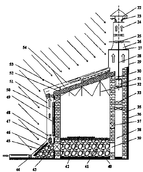
[0040] Embodiment 4: on the basis of embodiment 1, will be in figure 1 The heat exchanger 6 in the water tank 7 is removed, and the water pump 3 directly pumps the water in the water tank into the U-shaped pipe 1, which can improve thermal efficiency. At this time, the expansion tank 4 can also be omitted in the pipeline to form a solar direct heating system. . It should be noted that although this direct heating system is simple and efficient, it has the problem of water scaling in the U-shaped pipe and the problem of preventing the water in the pipe from freezing in winter.


PUM


Abstract

A solar energy and building integrated hot air power generation, ventilation and heating system comprises a house body. The house body comprises a foundation, walls, doors, windows and a solar hot air power generation, ventilation and heating system body. The solar hot air power generation, ventilation and heating system body comprises a solar energy ground collector, a solar energy outer wall collector, a solar energy roof collector, a solar hot air power generator, a solar heating device, a solar ventilating device and a solar hot air water heating device. The solar hot air power generation, ventilation and heating system has the advantages that the features of solar energy is effectively used, solar energy hot air is used for heating domestic hot water, ventilating, cooling, power generating and heating, solar energy air collectors are integrated with a building, the system is low in cost, safe, reliable, good in stability and capable of comprehensively utilizing solar energy all the year round, and the domestic hot water supply, winter heating, summer power generation, ventilation and cooling of the single building in northern areas can be achieved.

Description

technical field [0001] The invention relates to the technical fields of solar hot air power generation and solar heating and ventilation, in particular to a system combining solar energy and building integrated hot air power generation and building heat storage and heating. Background technique [0002] From the perspective of solar thermal power generation technology, the combination of existing solar thermal power generation technology and buildings is limited to the installation of solar collectors or solar chimneys on the roof or on the exterior walls of high-rise buildings, without effectively combining with the building's functions . Among the representative articles are: 2008 Huazhong University of Science and Technology doctoral dissertation "Based on Western Solar Chimney Thermal Airflow Power Generation and Application Research" proposed three mountain compound solar thermal airflow power generation systems, 2010 Qingdao University of Science and Technology Master'...

Claims


Application Information

Patent Timeline
Patent Type & Authority Applications(China)
IPC IPC(8): E04D13/18E04F17/04F03G6/06F24J2/26F24J2/30F24J2/34F24S10/30F24S10/75
CPCY02E10/44Y02E10/46Y02B10/10Y02B10/20Y02B10/30Y02E10/50
Inventor 王克振
Owner 山西奥通光热技术有限公司
Why Eureka
Try Eureka