A surface plasmon-enhanced needle tip and a needle-tip enhancement method

A surface plasmon, needle tip technology, applied in optical components, scanning probe technology, scanning probe microscopy, etc., can solve the problems of difficulty in forming a fast scanning array structure, difficulty, and long needle tip length, and achieve easy formation of large The effect of area tip arrays, increased scanning speed, improved signal-to-noise ratio and sensitivity

Active Publication Date: 2016-03-30
THE NAT CENT FOR NANOSCI & TECH NCNST OF CHINA
View PDF6 Cites 1 Cited by
  • Summary
  • Abstract
  • Description
  • Claims
  • Application Information

AI Technical Summary

Problems solved by technology

However, this kind of needle tip requires a small incident optical spot and precise spot positioning, and the length of the needle tip is too long, the SPPs attenuation is obvious, and it is difficult to form a fast-scanning array structure, which brings great difficulties to practical use.

Method used


Image

  • A surface plasmon-enhanced needle tip and a needle-tip enhancement method
  • A surface plasmon-enhanced needle tip and a needle-tip enhancement method
  • A surface plasmon-enhanced needle tip and a needle-tip enhancement method

Examples


Embodiment 1

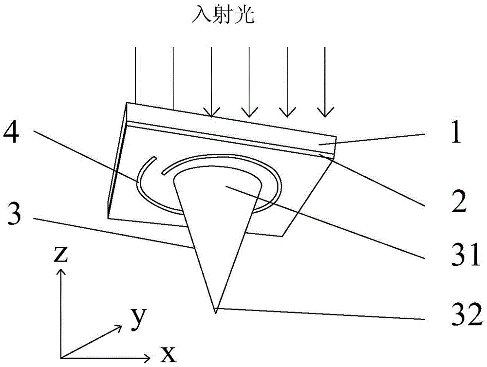
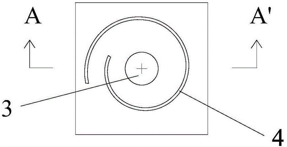
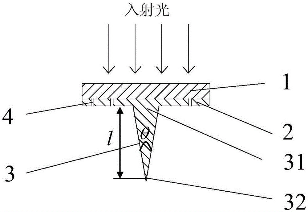
[0081] Embodiment 1 provides a surface plasmon enhanced needle tip, Figure 1a Schematic diagram illustrating the three-dimensional structure of the enhanced needle tip with the illumination direction of the incident light ( Figure 1a A schematic diagram of the three-dimensional structure of the enhanced needle tip provided in Example 1); Figure 1b Schematic illustration of a slit that enhances the helical structure machined on the tip structure ( Figure 1b Bottom view of the enhanced needle tip provided for Example 1); Figure 1c Schematic diagram illustrating the hierarchical structure of the enhanced tip structure ( Figure 1c The front cross-sectional view of the enhanced needle tip provided for Example 1);

[0082] Such as Figure 1a , Figure 1b , Figure 1c It can be seen that the surface plasmon-enhanced tip provided in this embodiment includes a transparent substrate 1, a metal film 2 fabricated on one side of the transparent substrate 1, and a metal tip 3 conne...

Embodiment 2

[0101] Embodiment 2 provides a surface plasmon-enhanced needle tip. The difference from Embodiment 1 is that the slit of the helical structure processed on the metal film is right-handed (rotating clockwise), and the slit of the helical structure The slit width is 50nm, the number of turns is 10, the minimum length (inner radius) between the first turn of the helical structure and the center of the helix is ​​550nm, and the pitch is 360nm.

Embodiment 3

[0102] Embodiment 3 provides a surface plasmon-enhanced needle tip. The difference from Embodiment 1 is that the slit width of the slit of the helical structure processed on the metal film is 400 nm, and the number of turns is 1. The first slit of the helical structure The minimum length (inner radius) of one turn from the center of the helix is ​​10 μm, and the helix pitch is 740 nm.


PUM

PropertyMeasurementUnit
widthaaaaaaaaaa
distanceaaaaaaaaaa
thicknessaaaaaaaaaa

Abstract

The invention relates to a surface plasmon polariton enhancement needlepoint which comprises a transparent substrate (1) used for incidence of light, a metal film (2) arranged on one side of the transparent substrate and provided with a slit of a spiral structure, and a metal needlepoint body (3) which comprises a pointed portion and a root portion of the metal needlepoint body, wherein the root portion is connected with the metal film and located in the center of the spiral structure. The needlepoint enhancement effect of the enhancement needlepoint is good, needlepoints of three orders of magnitude can be enhanced, the resolution ratio of 0.03lambda0 can be achieved, the enhancement depth reaches 50 nm, the signal-to-noise ratio and sensitivity are greatly improved, operation is convenient and easy to achieve, large-area needlepoint arrays are easy to form, and the scanning speed is improved.

Description

technical field [0001] The invention relates to a surface plasmon excitation structure, which belongs to the field of near-field optical enhancement technology. Specifically, the invention relates to a surface plasmon enhanced needle tip, an enhanced needle tip assembly and a needle tip enhancement method, especially a device with A surface plasmon-enhanced tip with a helical structure, an enhanced tip component, and a tip-enhanced method. Background technique [0002] With the development of near-field optics and nanotechnology, higher and higher requirements are put forward for the detection accuracy of super-resolution. The development of probe technology provides an effective means to solve this problem. However, there is an inherent contradiction between the size of the probe and the detection intensity, which hinders the development of probe technology to a certain extent. In recent years, the rapid development of probe tip enhancement technology provides new ideas f...

Claims


Application Information

Patent Timeline
Patent Type & Authority Patents(China)
IPC IPC(8): G01Q60/22G02B5/00
Inventor 陈东学苗俊杰刘前
Owner THE NAT CENT FOR NANOSCI & TECH NCNST OF CHINA
Why Eureka
Try Eureka