IC chip and control circuit of LED directly driven by electronic ballast

An electronic ballast and rectifier circuit technology, applied in the direction of electric lamp circuit layout, electric light source, lighting device, etc., can solve the problems of power loss, air pollution, excessive heat generation, etc., and achieve low consumption, long service life, and low heat generation Effect

Active Publication Date: 2014-06-04
ZHEJIANG FUCHUN LIGHTING CO LTD
View PDF3 Cites 6 Cited by
  • Summary
  • Abstract
  • Description
  • Claims
  • Application Information

AI Technical Summary

Problems solved by technology

[0004] The purpose of the present invention is to solve the power loss of various lighting technologies driven by existing electronic ballasts, especially the resistance elements in which more power will be consumed and heat will be more , short life and air pollution problems, provide an electronic ballast with less consumption, less heat generation, simple components, easy integration, and long service life to directly drive LED IC chips and their control circuits

Method used


Image

  • IC chip and control circuit of LED directly driven by electronic ballast
  • IC chip and control circuit of LED directly driven by electronic ballast

Examples


Embodiment 1

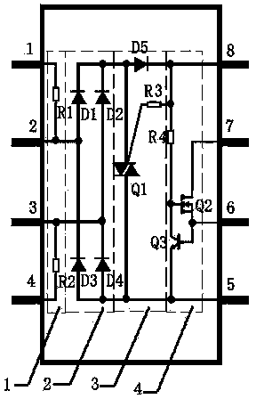
[0019] An electronic ballast directly drives an IC chip of an LED (see attached figure 1 ), is an eight-pin package chip, including four input pins and four output pins, and also includes a protection circuit 1, a rectifier circuit 2, a no-load protection circuit 3 and a constant current source circuit 4, the input terminal of the protection circuit and the input pin The pins are connected, and the output end of the protection circuit is connected with the input end of the rectification circuit. The input end of the rectification circuit 2 is connected to the input pin through the protection circuit 1, the output end of the rectification circuit 2 is connected to the input end of the constant current source circuit 4 through the no-load protection circuit 3, and the output end of the constant current source circuit 4 is connected to the output pin connection.

[0020] The protection circuit 1 includes a resistor R1 and a resistor R2. One end of the resistor R1 is connected to...

Embodiment 2

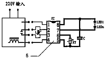
[0028] This embodiment is basically the same as Embodiment 1, except that the resistor R3 in this embodiment has a resistance value of 330K ohms, and the resistor R4 has a resistance value of 2M ohms. The inductor L in this embodiment is a variable inductor, and the resistor RT is a variable resistor.

[0029] In this embodiment, the user can adjust the output current by adjusting the inductance L and the resistance RT, so that various LED circuits can output matching driving currents.

[0030] This embodiment can solve the problems of large power loss, short life and air pollution of various lighting technologies driven by existing electronic ballasts. This embodiment consumes less, generates less heat, has simple components, is easy to integrate, and is bidirectional Thyristor Q1 works in a semi-conducting state, plays the role of no-load protection, and has a long service life. In this embodiment, the user can freely adjust the output power and constant current output throu...


PUM


Abstract

The invention relates to an IC chip and control circuit of an LED directly driven by an electronic ballast. The IC chip and the control circuit of the LED are capable of solving problems, which exist in the prior different illumination lamps driven by electronic ballasts, that power loss is high, service life is short and air is polluted. Key points of the technical scheme are as follows: the IC chip includes an input pin and an output pin and also includes a rectifying circuit, a no-load protection circuit and a constant-current-source circuit. An input end of the rectifying circuit is connected with the input pin and an output end of the rectifying circuit is connected with an input end of the constant-current-source circuit through the no-load protection circuit. An output end of the constant-current-source circuit is connected with the output pin. The control circuit includes an output-power control circuit at an output end of the electric ballast, a filtering circuit rectified by the IC chip and a constant-current size control circuit of the IC chip. Through the IC chip and the control circuit of the LED directly driven by the electronic ballast, a user is enabled to adjust freely the size and an output power and the output size of a constant current and are suitable for an LED circuit and bring convenience to direct replacement of the prior different kinds of fluorescent lamps, metal halide lamps and sodium lamps driven by electronic ballasts.

Description

technical field [0001] The invention relates to an IC chip and its control circuit, in particular to an IC chip and its control circuit for an electronic ballast directly driving an LED. Background technique [0002] LED has the advantages of low power consumption and long service life, and has been widely used in lighting, display and other fields, such as LED lighting, LED display screen, LED lighting and so on. With the country's increasing emphasis on green light sources, the market and application prospects of LED products are very broad. Since the LED is driven by DC voltage, the mains voltage cannot be directly used, and the LED drive power supply that converts the mains voltage into a DC voltage must be used. The current LED drive power supply is basically a constant current drive power supply in the form of a switching power supply, but it generally has the disadvantage of high cost. As we all know, AC electronic ballasts for fluorescent lamps have a development h...

Claims


Application Information

Patent Timeline
Patent Type & Authority Applications(China)
IPC IPC(8): H05B37/02
Inventor 罗正华
Owner ZHEJIANG FUCHUN LIGHTING CO LTD
Why Eureka
Try Eureka