[0027] In order to make the above objectives, features and advantages of the present invention more obvious and understandable, the present invention will be further described in detail below in conjunction with the accompanying drawings and specific embodiments.
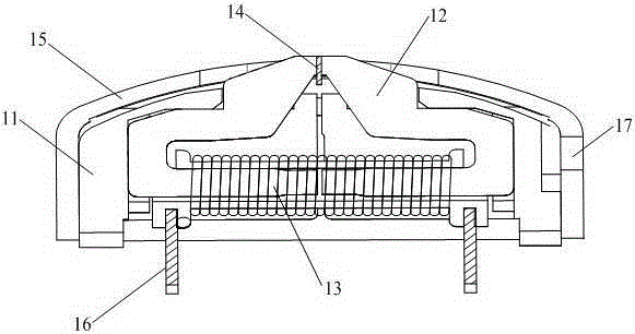
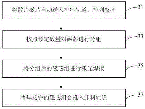
[0028] A magnetic card head generally requires 2-6 magnetic core groups, and each magnetic core group is composed of several scattered magnetic cores. The specific number depends on the shape, thickness and product model of the magnetic core. Scattered piece magnetic cores are thin parts with small size. If combined by manual operation, it is time-consuming and labor-intensive. However, the combination process of the magnetic core is a key process in the production process of the magnetic card head. To this end, the present invention provides a fully automated magnetic core assembly method and assembly system of the magnetic card head. First introduce the magnetic core assembly method of the magnetic card head provided by the present invention, refer to image 3 , Shows a flowchart of an embodiment of the magnetic core assembly method of the magnetic card head of the present invention, including:
[0029] Step 31: Automatically feed the scattered magnetic cores into the discharge track and arrange them neatly.
[0030] Step 31 is the discharging step, specifically: pour the scattered magnetic cores into the vibrating disk, and the vibrating disk will continuously send the magnetic cores into the discharging rail through resonance, and arrange them neatly on the rail, and then pass through the pushing trough and pushing The material manipulator pushes the magnetic core to the design position. Among them, the discharge speed can be controlled by adjusting the resonance frequency. In addition, the resonant frequency setting value can also be adjusted artificially according to the shape of the magnetic core. The above-mentioned designated position may be the design position of the laser welding process or the design position of the extrusion shaping process.
[0031] In the embodiment of the present invention, a double-rail vibration discharging machine is used for discharging, that is, the magnetic core discharging adopts a dual-rail design. The pushing groove is provided with two left and right grooves. When one groove is butted with the guide rail, the chip on the guide rail is pushed into the pushing groove under the drive of the discharging machine to complete the feeding process on one side. The above-mentioned pushing trough is in the middle position by default and can be moved left and right. When feeding the material on the left side of the pusher, the pusher manipulator can push the magnetic core in the right side of the pusher to the specified position; when the right side of the pusher feeds, the pusher manipulator can move the left side of the pusher Push the magnetic core to the designated position.
[0032] Step 33: Group the magnetic cores according to a predetermined number.
[0033] In the embodiment of the present invention, a group of 7 magnetic cores is taken as an example for grouping. The specific steps are as follows: visual monitoring is performed by using an optical detection device to accurately distinguish the number of magnetic cores. In this step, mechanical sensing devices can also be used for grouping. After grouping, the manipulator will transport a corresponding number of magnetic cores to the design position of the welding tool.
[0034] In the present invention, optical detection devices may be used to group the magnetic cores according to a predetermined number. The above-mentioned optical detection devices may be CCD (Charge Coupled Device) detection devices or grating counting devices. Among them, the working principle of the CCD detection device is: use the photoelectric conversion principle to collect the data of the number and position of the magnetic core, and then transfer it to the processor terminal, and the processor calculates and gives the next operation instruction. In order to ensure accurate data capture, a CCD with more than 380,000 pixels and a sensitivity of 2 to 3 Lux should be selected, and there should be a good light source around it.
[0035] Step 35: Laser welding the grouped magnetic core groups.
[0036] Specifically, the manipulator pushes the grouped magnetic core groups to the design position, and at the design position, the laser welding head performs laser welding on the magnetic core group.
[0037] In the embodiment of the present invention, when laser welding is performed on the magnetic core group, at least two laser welding heads are used to perform gap welding on the magnetic core group, and the step pitch is set to the thickness of a single magnetic core. The principle of laser welding is to radiate a high-intensity laser beam to the surface of the metal. Through the interaction between the laser and the metal, the metal absorbs the laser and converts it into heat to melt the metal and cool and crystallize to form a welding spot. Pic 4-1 A schematic diagram of the position of the magnetic core laser welding is shown. In the embodiment of the present invention, the laser welding is performed at three positions A, B, and C of the magnetic core. Figure 4-2 A schematic diagram of the magnetic core assembly after laser welding is shown. In the embodiment of the present invention, 7 magnetic cores are welded as a group to form a magnetic core group.
[0038] The laser used in this design can be a high-power CO 2 The laser can also be a high-power YAG laser or other lasers. The laser power density output by the laser welding head is not less than 10w/cm 2 , The pulse width is 5~15ms, and the optimal value is determined according to the shape of the magnetic core. Laser welding can also use continuous laser, with a spot diameter ranging from 0.2mm to 2mm.
[0039] When laser welding, the specific requirements are as follows:
[0040] ①The pieces are arranged neatly, and the misalignment does not exceed 0.015mm.
[0041] ②The position deviation does not exceed 0.1mm.
[0042] ③The number of beam focal spots is at least 2, and the position selection does not hinder the subsequent process assembly.
[0043] ④The bonding force between the magnetic cores is not less than 5N.
[0044] In addition, it should be noted that under the monitoring of the CCD detection device, step 33 and step 35 are performed at the same time, that is, the function of chip grouping is realized while welding is realized. Here, a group of 7 magnetic cores is taken as an example for specific explanation. On the laser welding tooling, the three laser welding heads move automatically under the control of the program, and each adjacent two pieces are combined by 3 laser welding points. At the same time, after the laser welding head has continuous gap welding for 6 times, it skips one step and performs the next set of welding. Therefore, the magnetic core grouping is automatically realized while the magnetic core welding is implemented.
[0045] In addition, the CCD detection device can also be used to monitor the welding status of the magnetic core. If the welding is found to be poor, it can promptly alarm.
[0046] Step 37: Push the welded magnetic core assembly into the discharge track.
[0047] Specifically, the push block pushes the welded magnetic core assembly into the discharge track, and then the magnetic core assembly slides into the receiving container.
[0048] Reference Figure 5 , Shows a schematic diagram of another embodiment of the magnetic core assembly method of the present invention, in image 3 On the basis of the illustrated embodiment, between steps 33 and 35, a step 34 is added: squeezing the magnetic core group neatly.
[0049] Step 34 is specifically: the pressing component squeezes the magnetic core group pushed to the design position neatly to ensure close contact between the chips. The addition of step 34 further ensures that the magnetic core assembly is arranged neatly before welding, and there is no dislocation.
[0050] For the laser welding monitored by the CCD detection device, since the magnetic core grouping is completed at the same time as the laser welding, the extrusion shaping step 34 is set before the step 33, that is, the overall magnetic core before grouping is extruded and shaped.
[0051] In summary, the magnetic core assembly method of the magnetic card head provided by the present invention uses laser welding technology to weld the magnetic core assembly together, which effectively prevents the thin and small magnetic core from being scattered during the traditional magnetic core assembly process. The appearance of undesirable phenomena such as chipping and dislocation. In the subsequent process, the welded magnetic core assembly is embedded in the holder, so that the electromagnetic performance of the magnetic core is completely released and the yield of the product is improved. In addition, the magnetic core combination method provided by the present invention is realized through a fully automated system, which not only saves a lot of human resources, but also effectively improves the production efficiency of the product.
[0052] For the foregoing method embodiments, for the sake of simple description, they are all expressed as a series of action combinations, but those skilled in the art should know that the present invention is not limited by the described sequence of actions, because according to the present invention, Some steps can be performed in other order or simultaneously. Secondly, those skilled in the art should also know that the embodiments described in the specification are all preferred embodiments, and the involved actions and modules are not necessarily required by the present invention.
[0053] Corresponding to the magnetic core assembly method of the magnetic card head, the present invention also provides a magnetic core assembly system of the magnetic card head. Image 6 The shown structural block diagram of the magnetic core assembly system of the present invention includes:
[0054] The discharging device 61 is used to automatically feed the bulk magnetic cores into the discharging track and arrange them neatly;
[0055] In this implementation, the discharging device may include a vibrating disk, a magnetic core discharging machine, a pushing trough, and a pushing manipulator.
[0056] The discharging device 61 is used to automatically realize the discharging process, and its working process is: the scattered magnetic cores are poured into the vibrating disk, and the vibrating disk continuously sends the magnetic cores into the discharging guide rail through resonance, and the arrangement is neat. The magnetic core discharging machine adopts a double guide rail design, and the pushing groove is also a double groove design, which can move left and right. When the left slot of the push chute is docked with the left rail for feeding, the pushing manipulator can push the magnetic core in the right slot of the push chute to the specified position; when the right slot of the push chute is docked with the right rail When feeding, the pushing manipulator can push the magnetic core in the left slot of the pushing slot to the specified position. The above-mentioned designated position may be a design position for positioning and shaping, or a design position for laser welding. Adopting the double discharge guide rail design in the discharging device 61, the pushing trough is switched from left to right, and the pushing manipulator circulates in this way, always maintaining a continuous working state, without waiting for discharging. It can save discharge time and improve discharge efficiency.
[0057] The pressing manipulator 62 is used to squeeze the magnetic core neatly.
[0058] The working process is: when the magnetic core is pushed to the design position, the automatic control device sends instructions to the pressing manipulator to carry out the extrusion and shaping operation.
[0059] The above-mentioned design positions are specially designed positions for the extrusion and shaping process. In the entire automated operating system, only when the magnetic core group is in this position, the automated control device will issue instructions to the press manipulator to perform extrusion and shaping operations.
[0060] The optical detection device 63 is used for accurately distinguishing the number of magnetic cores when the magnetic cores are grouped.
[0061] The above-mentioned optical detection device may be a CCD detection device or a grating counting device or the like.
[0062] The CCD detection device uses the photoelectric conversion principle to collect the data of the number and position of the magnetic core, and then transmits it to the processor of the automatic control device. The processor calculates and gives the next operation instruction. In order to ensure accurate data capture, you need to choose a CCD with more than 380,000 pixels, a sensitivity of 2~3 Lux or better, and a good light source around it.
[0063] The laser welding device 64 uses laser welding technology to perform laser welding on the magnetic core assembly.
[0064] The above-mentioned laser welding device includes at least two laser welding heads, and the laser welding device adopts pulse laser welding or continuous laser welding. The welding step is set to the thickness of one core. Among them, the output power density of the pulse laser welding head is not less than 10w/cm 2 , The output pulse width range is: 5~15ms. When continuous laser welding, the diameter range of the spot is selected between 0.2~2mm.
[0065] In the embodiment of the present invention, the laser welding device 64 uses three laser welding heads to weld the magnetic core assembly at the same time. The step is the thickness of the magnetic core. Every 6 times of welding, one step is skipped, thereby forming one by 7 Magnetic core group composed of magnetic cores.
[0066] The pushing block 65 is used to push the welded magnetic core assembly into the discharge track.
[0067] The automation control device 66 is used to control the above-mentioned devices to perform automatic operations.
[0068] The automation control device 66 communicates with each of the above-mentioned devices, monitors the working status of each device and issues control instructions to each device, triggering each device to work according to the set program.
[0069] The working process of the magnetic core assembly system of the magnetic card head is: under the control of the automatic control device 66, the discharging device 61 uses a vibrating disk to continuously send the magnetic cores into the discharging track and arrange them neatly. The pressing manipulator 62 pushes the magnetic cores to the design position and squeezes them neatly to ensure that the magnetic cores are arranged neatly and in close contact. Under the visual monitoring of the optical detection device 63, the number of magnetic cores is accurately distinguished, and the laser welding device 64 performs laser welding on the magnetic cores, and completes the process of grouping and combining the magnetic cores sequentially or simultaneously. The pushing block 65 pushes the welded magnetic core assembly into the discharge track, and then the magnetic core assembly slides into the receiving container.
[0070] In another embodiment of the magnetic core assembly system of the magnetic card head of the present invention, the above-mentioned CCD detection device is also used to detect the laser welding state of the magnetic core. Figure 7 A schematic diagram of the working flow of the CCD detection device in this embodiment is shown:
[0071] The CCD detection device monitors the number of magnetic cores after grouping. If the number of magnetic cores is accurate, it sends a signal to the automatic control device to instruct the laser welding device to laser weld the magnetic core group. If the number of magnetic cores is found to be incorrect, the automatic control device is triggered to issue an alarm signal. During the laser welding process, the laser welding quality is monitored. If the welding quality is qualified, a signal is sent to the automatic control device to instruct the next operation. If the welding quality is found to be unqualified, the automatic control device is triggered to issue an alarm signal.
[0072] It can be seen that the CCD detection device not only ensures the accuracy of magnetic core grouping, but also ensures the quality of laser welding and ensures the ideal yield of products.
[0073] In a word, adopting the magnetic core assembly system of the magnetic card head provided by the present invention can realize the fully automated operation of the magnetic core assembly, effectively saving human resources, reducing labor costs, and improving the production efficiency of products. A laser welding device is used to weld the magnetic core groups together to ensure that the magnetic cores are in close contact, effectively avoiding the misalignment and fragmentation of the magnetic core groups, and improving the yield of products.
[0074] The various embodiments in this specification are described in a progressive manner. Each embodiment focuses on the differences from other embodiments, and the same or similar parts between the various embodiments can be referred to each other. As for the system embodiment, since it is basically similar to the method embodiment, the description is relatively simple, and for related parts, please refer to the description of the method embodiment.
[0075] The magnetic core assembly method of the magnetic card head and the magnetic core assembly system of the magnetic card head provided by the present invention are described in detail above. In this article, specific examples are used to illustrate the principle and implementation of the present invention. The description of the above embodiments is only used to help understand the method and core idea of the present invention; at the same time, for those of ordinary skill in the art, according to the idea of the present invention, there will be changes in the specific implementation and the scope of application. In summary, the content of this specification should not be construed as limiting the present invention.