


Quick Research
Generate reliable direction feasibility study reports for your R&D in just a few steps.

Technical Q&A
Discover and master advanced knowledge NOW. Basics, ideas, possibilities, all at once.

Find Solutions
As an expert in R&D theories, this can generate solutions to your technical problems instantly.

Evaluate Feasibility
Analyze your overall solution with one click, know your potential R&D risks in advance.

Monitor Landscape
Get weekly tech updates, stay abreast of the latest tech innovations and key insights.
A magnetic field demulsifier
A technology of demulsifier and electric field, which is applied in the direction of electricity/magnetic dehydration/demulsification, etc., can solve the problems of large volume and complex structure, and achieve the effects of small volume, improved separation efficiency, and convenient installation and use
- Summary
- Abstract
- Description
- Claims
- Application Information
AI Technical Summary
Problems solved by technology
Method used
Image

Examples
Embodiment 1
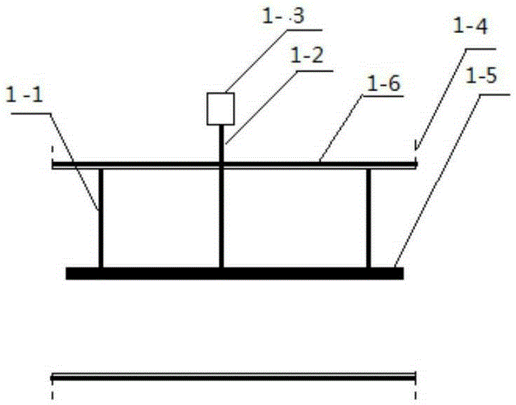
[0046] Such as figure 1 As shown, a magnetic field demulsifier is mainly used in places with small pipe diameters and low electric field strength requirements. The central metal electrodes 1-5 located in the center of metal pipe sections 1-4 with flanges are hung with insulation 1 -1 is fixed on the top of the pipe section, the electrical connector 1-3 is connected to the central metal electrode 1-5 through the electrode rod 1-2, the electrode rod 1-2 is insulated from the pipe section, the pipe section is grounded, and the electrical connector 1-3 is connected to the output end of the transformer connected. Ring magnets 1-6 are located on the periphery of the flanged metal pipe section 1-4.
[0047] The ring magnets 1-6 are ring monopole magnets. The ring magnets 1-6 are permanent magnets or electromagnets.
[0048] The power supply transformer is a single-phase transformer, a three-phase transformer, a pulse transformer, an AC transformer or a DC transformer.
[0049] An...
Embodiment 2
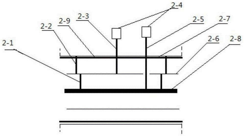
[0051] Such as figure 2 As shown, a magnetic field demulsifier is mainly used in places with large pipe diameters and high electric field strength requirements. The center electrode 2-8 located in the center of the pipe section 2-7 with flange is insulated and suspended by the center electrode 2- 1. Fixed on the top of the ring electrode bar 2-6, the ring electrode bar 2-6 is insulated and hung by the electrode bar 2-2 is fixed on the top of the pipe section, the ring electrode bar 2-6 and the pipe section 2-7 with flange are concentric rings Structure, the distance between the metal electrode 2-8 in the center of the pipe section and the ring electrode column 2-6, the distance between the ring electrode column 2-6 and the inner wall of the pipe section 2-7 with flange is equidistant, and the electrical connector 2-4 passes through the center Electrode The electrode rod 2-5 is connected to the central electrode 2-8, and the electrode rod 2-3 is connected to the ring electrode...
Embodiment 3
[0055] A magnetic field demulsifier mainly used in places with large pipe diameters and high electric field strength requirements, including metal pipe sections with flanges; electrodes are arranged in the metal pipe sections with flanges, and the electrodes are suspended through insulation The electrode is fixed on the top of the metal pipe section with flange; the electrode is connected with the power supply transformer through the electrode rod; the metal pipe section with flange is grounded; the periphery of the electrode is provided with a ring magnet.
[0056] The electrodes include a central metal electrode arranged in the center of the flanged metal pipe section and two annular electrode columns surrounding the central metal electrode. The middle metal electrode is fixed on the inner ring electrode bar through the insulating hanger, the inner ring electrode bar is fixed on the outer ring electrode bar through the insulating hanger, and the outer ring electrode bar is fi...
PUM
 Abstract
Description
Claims
Application Information
 - R&D Engineer
- R&D Manager
- IP Professional
- Industry Leading Data Capabilities
- Powerful AI technology
- Patent DNA Extraction
Browse by: Latest US Patents, China's latest patents, Technical Efficacy Thesaurus, Application Domain, Technology Topic, Popular Technical Reports.
© 2024 PatSnap. All rights reserved.Legal|Privacy policy|Modern Slavery Act Transparency Statement|Sitemap|About US| Contact US: help@patsnap.com